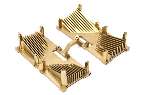
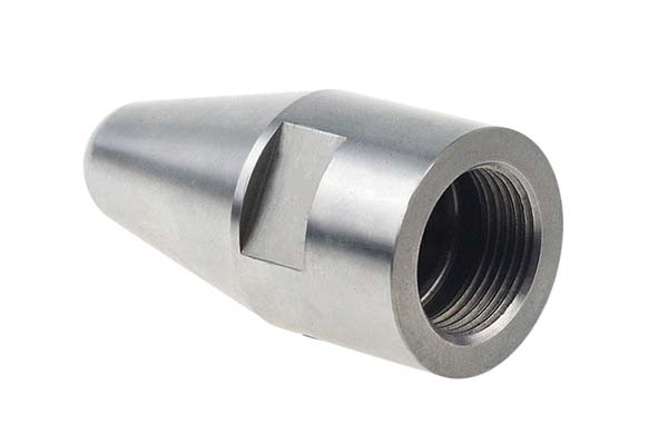
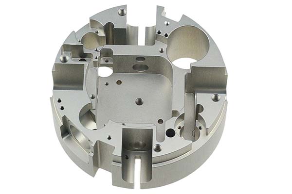
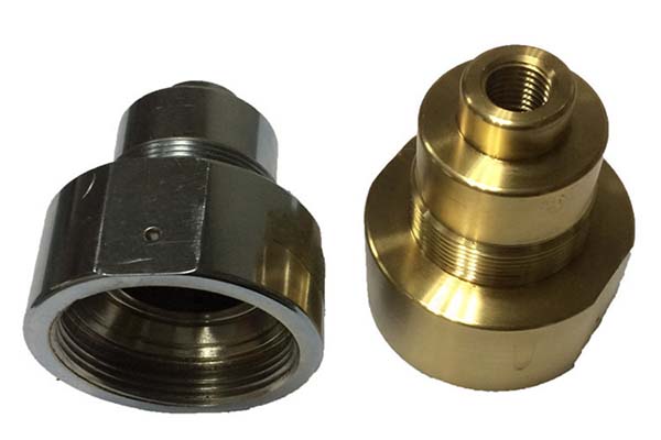
CNC machining of PVDF (polyvinylidene fluoride) presents unique challenges stemming from its exceptional material properties. Its high chemical resistance and inertness—key advantages for chemical processing applications—make it highly abrasive, accelerating tool wear and reducing tool life compared to softer plastics. PVDF’s combination of mechanical strength and toughness causes it to deform under cutting forces, leading to poor dimensional accuracy if machining parameters are not optimized. Additionally, its thermal stability (continuous use up to 150°C) belies a tendency to soften under prolonged machining heat, resulting in surface defects like smearing or warping. Achieving tight tolerance verification is further complicated by its moderate flexural modulus; residual stresses from machining can cause subtle dimensional shifts, requiring careful toolpath optimization and post-machining cooling. This guide addresses these pain points, offering expert strategies to master CNC machining of PVDF.
Material Characteristics of PVDF
PVDF (polyvinylidene fluoride) boasts properties that make it indispensable in demanding industrial applications, while influencing its machinability:
- Chemical and corrosion resistance: Exceptional resistance to acids, bases, solvents, and halogenated compounds, making it ideal for chemical processing and water treatment components.
- High purity: Low extractable content and non-toxicity (FDA-compliant grades) suit medical devices and food processing applications, requiring strict machining cleanliness.
- Dielectric properties: Excellent electrical insulation and low dielectric constant make it suitable for electrical components and high-frequency applications.
- UV resistance: Outstanding resistance to ultraviolet radiation, extending service life in outdoor aerospace components and automotive parts.
- Mechanical strength: Tensile strength of 40-50 MPa and flexural modulus of 2-3 GPa provide a balance of rigidity and toughness, though this toughness complicates cutting.
- Thermal stability: Withstands continuous temperatures up to 150°C, with short-term exposure to 170°C, though machining heat above 180°C causes softening.
| Property | PVDF | PTFE | HDPE |
| Chemical Resistance | Excellent | Excellent | Good |
| Thermal Stability (°C) | 150 | 260 | 120-130 |
| Tensile Strength (MPa) | 40-50 | 20-30 | 20-30 |
| Density (g/cm³) | 1.77-1.80 | 2.1-2.3 | 0.941-0.965 |
CNC Machining Techniques for PVDF
The CNC machining techniques for PVDF require tailored approaches to handle its strength and abrasiveness:
- Milling: The primary process, using rigid setups and sharp tools to minimize deformation. A spindle speed of 4000-8000 RPM and feed rate of 0.1-0.2 mm/tooth works well, with a depth of cut of 0.5-2 mm for roughing and 0.1-0.3 mm for finishing. Climb milling reduces material pull, ensuring clean cuts in precision machining of semiconductor industry components.
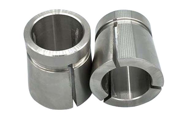
- Turning: Suitable for cylindrical PVDF parts like valves or bushings, with spindle speed of 2000-5000 RPM and feed rate of 0.1-0.2 mm/rev. A positive rake angle (+5° to +10°) reduces cutting forces, minimizing work hardening.
- Drilling and engraving: Requires carbide tools with a 130° point angle to prevent delamination. Engraving uses polycrystalline diamond (PCD) tools at 8000-12000 RPM to achieve precise details in electrical components and medical devices.
- Surface finishing: Secondary processes like polishing or deburring remove micro-burrs, critical for cleanroom applications where particle generation must be minimized. Multi-axis machining centers ensure complex geometries are finished in one setup, reducing handling-related contamination.
Tool Selection for PVDF Machining
Tool selection is critical for efficient PVDF machining, balancing wear resistance and cutting performance:
- Carbide tools: The workhorse for PVDF machining, with tungsten carbide inserts (WC-Co) offering high hardness (90-92 HRA) to resist abrasion. Uncoated carbide prevents material adhesion better than coated variants, extending tool life by 30-50% in high-volume runs.
- Polycrystalline diamond (PCD) tools: Ideal for achieving Ra <0.8 μm surface finish in critical applications like semiconductor industry components, though higher cost limits use to precision requirements.
- High-speed steel (HSS) tools: Suitable for low-volume prototyping, though tool life is 5-10 times shorter than carbide due to PVDF’s abrasiveness.
- Tool geometry: 2-4 flutes with a high helix angle (35°-45°) improve chip evacuation, preventing re-cutting of abrasive particles. A sharp cutting edge (radius <0.02 mm) reduces deformation and heat generation.
- Tool wear management: Tool life averages 200-500 parts per edge for carbide tools, depending on cutting speed and part complexity. Regular inspection for flank wear (>0.2 mm) prevents surface defects.
Optimizing Machining Parameters for PVDF
Optimized machining parameters balance material removal, tool life, and part quality:
- Cutting speed: 100-200 m/min for carbide tools, 50-100 m/min for HSS—faster speeds reduce contact time, lowering heat buildup below PVDF’s softening point.
- Feed rate: 0.1-0.2 mm/tooth for milling, 0.1-0.15 mm/rev for turning, to minimize deformation while ensuring efficient chip evacuation.
- Depth of cut: 0.5-2 mm for roughing, 0.1-0.3 mm for finishing, distributing load evenly across the tool edge to prevent wear.
- Coolant usage: High-pressure coolant (30-50 bar) with deionized water or specialized fluorinated coolants (for high purity applications) flushes away chips and dissipates heat—critical for maintaining dimensional accuracy.
- Toolpath optimization: Circular interpolation and smooth transitions reduce sharp turns, lowering stress on PVDF parts and minimizing residual stresses that cause post-machining warping.
Applications of PVDF in CNC Machining
CNC machined PVDF parts excel in industries requiring chemical resistance, purity, and durability:
- Chemical processing: Valves, pumps, and tank liners leverage PVDF’s corrosion resistance, withstanding aggressive media in pharmaceutical and industrial chemical plants.
- Semiconductor industry: Wafer handling equipment and cleanroom fixtures use its high purity and low particle generation, meeting ISO Class 5 cleanroom standards.
- Medical devices: Surgical instrument components and fluid handling systems benefit from its biocompatibility (ISO 10993 compliance) and resistance to sterilization processes.
- Electrical components: Insulators, connectors, and cable jackets use its dielectric properties, performing reliably in high-voltage and high-frequency environments.
- Aerospace components: Structural parts and wire insulation leverage its UV resistance and thermal stability, withstanding extreme temperature fluctuations.
Quality Assurance in PVDF Machining
Rigorous quality assurance ensures PVDF parts meet stringent industry standards:
- Dimensional accuracy: Coordinate measuring machines (CMMs) with high-resolution probes verify tolerances (±0.02-0.1 mm), with measurements taken 2 hours after machining to account for stress relaxation.
- Surface roughness: Profilometers check for Ra 1.6-3.2 μm (standard) or Ra <0.8 μm (precision parts), ensuring no micro-burrs that could trap contaminants in cleanroom applications.
- Non-destructive testing (NDT): Ultrasonic testing detects subsurface defects in load-bearing parts like aerospace components, while visual inspections under magnification (20-50x) check for surface flaws.
- Cleanliness requirements: Parts for semiconductor industry and medical devices undergo ultrasonic cleaning and particle counting (≤10 particles/ft³ ≥0.5 μm), meeting ISO 14644-1 Class 5 standards.
- Statistical process control (SPC): Monitors machining parameters and part dimensions across production runs, reducing variation by 25-40% in critical applications.
Case Studies and Industry Examples
- Chemical processing components: A manufacturer reduced tool wear by 40% by switching to PCD tools and optimizing coolant usage with high-pressure deionized water. Tolerance verification improved from ±0.05 mm to ±0.02 mm, meeting ASME B46.1 standards.
- Semiconductor wafer carriers: By implementing toolpath optimization with arc transitions and reducing depth of cut to 0.3 mm, a supplier achieved Ra 0.4 μm surface finish and eliminated particle generation, increasing yield from 78% to 99%.
- Medical device manifolds: Using multi-axis machining and carbide tools with polished flutes, a contractor maintained high purity requirements (≤0.1 ppm extractables) while reducing cycle time by 30% via optimized feed rate and spindle speed.
Yigu Technology's Perspective
Yigu Technology specializes in CNC machining PVDF, leveraging expertise in handling its abrasiveness and toughness. We use carbide and PCD tools with optimized geometry to minimize tool wear, paired with CAD/CAM software for precision toolpath optimization. Our multi-axis machining centers ensure complex parts like chemical processing valves and semiconductor fixtures are machined accurately in one setup. Quality control includes CMM inspections, NDT, and cleanroom processing (ISO Class 5) for critical applications, ensuring compliance with cleanliness requirements. We tailor machining parameters to PVDF grades, balancing material removal and heat management to deliver parts with consistent dimensional accuracy and surface finish. Whether producing industrial components or medical devices, we deliver reliable, high-performance results by mastering PVDF’s unique machining challenges.
FAQ
- Why does PVDF cause rapid tool wear, and how to mitigate it?
PVDF’s abrasive structure and high mechanical strength accelerate wear. Mitigation involves using carbide or PCD tools, maintaining cutting speed of 150-200 m/min to reduce friction, and implementing high-pressure coolant to flush away abrasive chips—extending tool life by 30-50%.
- How to prevent heat-induced defects in PVDF machining?
PVDF softens above 180°C, causing smearing or warping. Prevention includes using spindle speed of 6000-8000 RPM, feed rate of 0.15-0.2 mm/tooth, and high-pressure coolant to dissipate heat. Toolpath optimization with minimal tool engagement time further reduces heat buildup.
- What tolerances are achievable in PVDF machining, and how to ensure consistency?
Standard tolerances are ±0.05-0.1 mm, with precision applications (e.g., semiconductor industry) reaching ±0.02-0.03 mm. Consistency requires rigid machining centers, PCD tools, post-machining stress relief (2 hours at 80°C), and SPC monitoring of machining parameters.
