Introduction
You have a part to make. Maybe it is a simple shaft. Maybe it is a complex aerospace component with internal cooling channels. The material could be soft aluminum or superalloy that resists cutting. The quantity might be one prototype or ten thousand production parts.
The machining method you choose will determine everything: accuracy, surface finish, cost, and delivery time. Choose wrong, and you face scrap, rework, and missed deadlines. Choose right, and production flows smoothly, parts meet specifications, and customers stay satisfied.
But with so many methods available—traditional cutting, advanced processes, additive manufacturing—how do you decide? This guide breaks down the options. You will learn what each method does well, where it falls short, and how to match the process to your specific requirements.
What Are Traditional Machining Methods?
Traditional machining removes material through mechanical cutting. A tool harder than the workpiece shears away material to create the desired shape. These methods have been refined over decades and remain the backbone of manufacturing.
Turning: For Cylindrical Parts
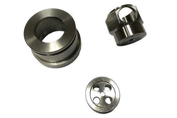
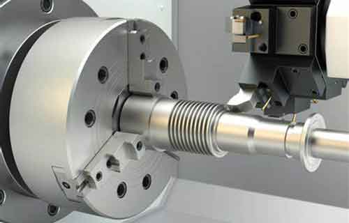
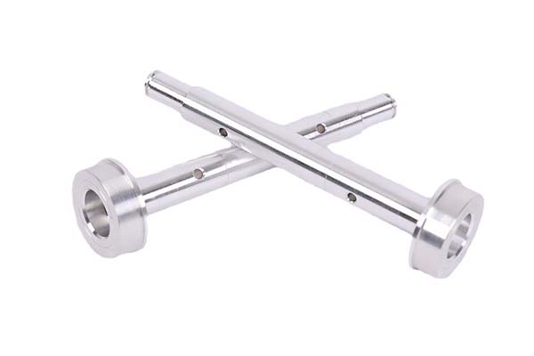
Turning rotates the workpiece while a stationary cutting tool removes material. It produces cylindrical shapes: shafts, bushings, threaded components, and round profiles.
Key parameters:
- Cutting speed: 50–500 m/min (depending on material)
- Feed rate: 0.1–0.5 mm/rev
- Depth of cut: 0.5–5 mm
A typical application: engine crankshafts. Automotive manufacturers turn millions of these annually, holding diameters to ±0.01 mm across high-volume runs.
Best for: Cylindrical parts, threads, tapers, and features of rotation.
Limitations: Complex non-cylindrical features require secondary operations.
Milling: For Complex Shapes
Milling uses a rotating multi-tooth cutter to remove material from a stationary workpiece. It creates flat surfaces, slots, pockets, and complex 3D contours.
Key parameters:
- Cutting speed: up to 1,000 m/min for some materials
- Feed rate: 0.05–0.5 mm per tooth
- Depth of cut: 0.1–5 mm
Three-axis mills handle most general work. Five-axis machines add rotational axes, allowing complex geometries in a single setup. An aerospace fitting that requires three setups on a three-axis machine completes in one setup on a five-axis—eliminating positioning errors.
Best for: Complex shapes, multi-surface parts, prototypes to production.
Limitations: Less efficient than turning for purely cylindrical parts.
Drilling: Creating Holes
Drilling creates round holes. While simple in concept, deep holes, precise diameters, and difficult materials demand attention to parameters.
Key parameters:
- Cutting speed for steel: 20–30 m/min
- Feed rate: 0.1–0.3 mm/rev
Peck drilling—withdrawing the drill periodically—clears chips and prevents heat buildup in deep holes. For precision holes, drilling may be followed by reaming or boring.
Best for: Holes of various depths and diameters.
Limitations: Standard drills produce holes with moderate accuracy; precision requires secondary operations.
Grinding: Achieving Surface Finish
Grinding uses an abrasive wheel to remove small amounts of material. It produces surface finishes that cutting tools cannot match—down to Ra 0.02 μm for critical applications.
Key parameters:
- Wheel speed: 30–60 m/s
- Depth of cut: 0.001–0.05 mm
Hydraulic valve manufacturers rely on grinding for sealing surfaces. A ground finish that holds pressure at 10,000 psi prevents leaks that would occur with milled surfaces.
Best for: Precision finishing, hard materials, tight tolerances.
Limitations: Slow material removal; primarily a finishing process.
Other Traditional Methods
| Method | Primary Use | Typical Application |
|---|---|---|
| Broaching | Internal/external shapes | Keyways, splines, gear profiles |
| Shaping | Flat surfaces | Large plates, machine ways |
| Planing | Large flat surfaces | Machine beds, rail surfaces |
| Sawing | Cutting to length | Bar stock, plates, structural shapes |
What Are Advanced Machining Methods?
Advanced methods address materials and geometries that traditional cutting cannot handle. They use thermal, chemical, or electrical energy rather than mechanical cutting.
Laser Cutting: Precision and Speed
Laser cutting uses a focused beam to melt, burn, or vaporize material. It achieves ±0.05 mm tolerance and cuts materials from thin foils to thick plates.
In electronics manufacturing, laser cutting creates intricate patterns on circuit boards. In sheet metal fabrication, it cuts complex contours in seconds that would take minutes with mechanical cutting.
Best for: Thin materials, complex contours, fast prototyping.
Limitations: Heat-affected zone; thickness limits; not for internal features.
Electrochemical Machining (ECM)
ECM removes material through an electrochemical reaction. The workpiece (anode) and tool (cathode) sit in an electrolyte. Current dissolves metal ions from the workpiece—no mechanical contact, no tool wear.
ECM achieves ±0.02 mm tolerance and machines hard materials that destroy cutting tools. Aerospace manufacturers use ECM for turbine blades made from superalloys like Inconel.
Best for: Hard materials, complex shapes, stress-free machining.
Limitations: High equipment cost; electrolyte disposal considerations.
Wire Electrical Discharge Machining (WEDM)
WEDM uses electrical discharges between a wire electrode and the workpiece to erode material. It cuts hardened steels, carbides, and conductive materials with ±0.005 mm accuracy.
Tool and die makers use WEDM for punch and die sets. A single wire path can cut complex contours that would require multiple operations with conventional methods.
Best for: Hard materials, intricate contours, precision dies.
Limitations: Conductive materials only; slower than mechanical cutting.
Abrasive Water Jet Machining
Abrasive water jet combines high-pressure water with abrasive particles. It cuts virtually any material—metal, stone, glass, composites—without generating heat.
No heat-affected zone means no metallurgical changes at the cut edge. This matters for materials sensitive to heat, like titanium and composites.
Best for: Heat-sensitive materials, thick sections, varied materials.
Limitations: Slower than laser for thin materials; abrasive disposal.
Electron Beam Machining (EBM)
EBM uses a high-energy electron beam to melt and vaporize material in a vacuum. It creates micro-features with high aspect ratios. Aerospace manufacturers use EBM for cooling holes in turbine blades—holes that traditional drilling cannot produce.
Best for: Micro-features, high-aspect-ratio holes.
Limitations: Vacuum required; high equipment cost.
Ultrasonic Machining (USM)
USM uses high-frequency vibrations (20–40 kHz) to drive an abrasive slurry against the workpiece. It machines hard, brittle materials like glass, ceramics, and carbides that resist conventional cutting.
Best for: Hard, brittle materials.
Limitations: Slow material removal; abrasive slurry management.
What Is Additive Manufacturing?
Additive manufacturing (3D printing) builds objects layer by layer from a digital model. Instead of removing material, it adds material only where needed.
Key Technologies
| Technology | Process | Best For |
|---|---|---|
| FDM (Fused Deposition Modeling) | Extrudes melted plastic filament | Prototypes, low-volume plastic parts |
| SLA (Stereolithography) | Cures liquid resin with laser | High-detail prototypes, smooth surfaces |
| SLS (Selective Laser Sintering) | Fuses powder with laser | Functional prototypes, complex geometries |
When to Use Additive vs. Traditional Machining
Additive excels at:
- Complex internal geometries impossible with subtractive methods
- Low-volume production where tooling costs are prohibitive
- Rapid prototyping to test form and fit
Traditional machining remains better for:
- High-volume production where economies of scale apply
- Tight tolerances (machining achieves ±0.005 mm; additive typically ±0.1 mm)
- Certain materials where additive options are limited
- Surface finish requirements that demand grinding or polishing
The reality: these methods complement each other. A part might be 3D printed as a prototype, then machined from billet for production. Or printed near-net-shape and finish-machined to critical tolerances.
What Process Parameters Determine Success?
Cutting Speed, Feed Rate, and Depth of Cut
These three parameters form the foundation of machining efficiency. The right combination balances material removal rate against tool life and surface quality.
Cutting speed too high: tool overheats, wears rapidly. Too low: inefficient, may cause work hardening.
Feed rate too high: poor surface finish, excessive tool load. Too low: rubbing instead of cutting, work hardening.
Depth of cut affects both material removal and cutting forces. Light passes may seem safer but can actually accelerate wear through prolonged rubbing.
Tool Geometry
Tool geometry influences every aspect of machining:
- Rake angle: Positive rake reduces cutting forces; negative rake adds edge strength
- Clearance angle: Prevents rubbing between tool and workpiece
- Cutting edge radius: Sharp edges cut cleanly but chip easily; radiused edges last longer
A well-designed tool geometry reduces cutting forces by 10–25% compared to generic tools, directly improving accuracy and tool life.
Cutting Forces and Temperature
Cutting forces deflect workpieces and tools. For slender parts, deflection can exceed tolerance limits. Strategies to manage forces include:
- Using sharp tools to reduce required force
- Climb milling instead of conventional milling
- Rigid setups with adequate clamping
Cutting temperature accelerates tool wear. For every 10°C increase in cutting temperature, tool life decreases by roughly 10–20% . Coolant strategies matter.
Surface Finish and Material Removal Rate
These two metrics often trade off against each other. A lower feed rate improves surface finish but reduces material removal rate. A higher cutting speed can improve both—up to the point where tool wear accelerates.
For a given operation, the optimal parameters balance:
- Required surface finish (Ra value)
- Production volume (time per part)
- Tool cost (wear rate)
What Equipment Makes Machining Possible?
Machine Tools
Lathes, milling machines, and drill presses form the traditional machine shop. Modern versions are CNC (Computer Numerical Control) —programmed to execute operations with high precision and repeatability.
CNC capabilities:
- Positioning accuracy: ±0.001–0.01 mm depending on machine
- Repeatability: within ±0.001 mm for high-end equipment
- Multi-axis: 3-axis for general work; 5-axis for complex geometries
A CNC milling machine can produce a part to ±0.01 mm accuracy across thousands of cycles, maintaining consistency that manual machining cannot match.
Cutting Tools and Holders
Cutting tools come in various materials:
- High-speed steel (HSS) : Economical, good for small batches
- Carbide: Harder, holds edge longer, preferred for production
- Coated carbide: AlTiN, TiCN coatings extend life by 40–60%
- Diamond: For abrasive materials, longest life
Tool holders affect accuracy as much as the machine itself. Shrink-fit and hydraulic holders provide the rigidity needed for precision work. A tool held loosely can introduce 0.02 mm runout—enough to scrap precision parts.
Coolant Systems
Coolant serves multiple purposes:
- Cools the cutting zone to prevent tool wear
- Lubricates to reduce friction and improve finish
- Flushes chips to prevent re-cutting
High-pressure coolant (70–120 bar) directed precisely at the cutting edge improves tool life by 30–50% compared to flood coolant.
Fixtures and Workholding
Workpieces must be held securely without distorting. Fixtures range from simple vises to custom-designed clamping systems. For thin-walled parts, inadequate clamping causes distortion during machining—leading to parts that measure correctly in the fixture but fail when released.
Measurement Tools
You cannot make what you cannot measure. Precision manufacturing relies on:
| Tool | Typical Accuracy |
|---|---|
| Micrometer | ±0.001 mm |
| Caliper | ±0.01 mm |
| CMM (Coordinate Measuring Machine) | ±0.0005 mm |
In-process probing on CNC machines measures critical features during machining, allowing adjustments before defects occur.
How Do You Ensure Quality and Accuracy?
Dimensional Accuracy and Tolerance
Dimensional accuracy measures how close the actual part is to the design. Tolerance defines the acceptable range. Aerospace components often require ±0.005 mm —tight enough that temperature changes during measurement matter.
Achieving tight tolerances requires:
- Rigid machines that resist deflection
- Proper tool selection to maintain cutting edge
- Stable workholding that doesn't distort parts
- Environmental control—temperature changes affect measurements
Surface Roughness
Surface roughness affects appearance, friction, sealing, and fatigue life. Rough surfaces concentrate stress, leading to premature failure in cyclic loading.
| Application | Target Ra (μm) |
|---|---|
| General machining | 1.6–3.2 |
| Decorative | ≤1.6 |
| Sealing surfaces | ≤0.8 |
| Bearings | ≤0.2 |
Geometric Tolerances
Beyond dimensions, parts must meet geometric tolerances: roundness, flatness, straightness, perpendicularity, parallelism. A shaft can measure the correct diameter but still fail if it is bent. Inspection methods for geometric tolerances include CMM scanning and dedicated gauges.
Quality Control Systems
Effective quality control operates at multiple levels:
- Raw material inspection: Verify composition and properties
- In-process inspection: Catch variations before they become defects
- First article inspection: Verify the first part against all specifications
- Final inspection: Confirm before shipment
Statistical Process Control (SPC) monitors production data in real time. When measurements trend toward limits, operators intervene before defects occur. One manufacturer reduced scrap by 40% using SPC.
Where Are Different Methods Applied?
Automotive Industry
High-volume production demands efficiency. Turning for shafts and gears. Milling for engine blocks and transmission cases. Grinding for bearing surfaces and valve seats. Advanced methods like ECM and WEDM appear for turbocharger components and fuel injection systems.
Aerospace Industry
Precision and material capability dominate. Five-axis milling for structural components. EDM and ECM for turbine blades in superalloys. Laser cutting for sheet metal components. Tolerances measured in microns; materials like titanium and Inconel require specialized approaches.
Electronics Manufacturing
Miniaturization drives methods. Laser cutting creates fine features on circuit boards. Micro-milling produces connector housings and enclosures. EDM creates micro-holes for vias and interconnects.
Medical Device Manufacturing
Biocompatibility and precision intersect. Micro-milling for surgical instruments. Grinding for implant surfaces. Swiss turning for bone screws and fasteners. Cleanroom conditions and validated processes ensure patient safety.
Tool and Die Making
Dies and molds demand extreme precision. WEDM cuts punch and die sets. Milling creates mold cavities. Grinding finishes critical surfaces. A die that produces millions of parts must maintain accuracy across its life.
Yigu Technology's Perspective
At Yigu Technology, we help clients navigate these choices daily. The right machining method balances part complexity, required accuracy, material properties, and production volume.
For plastic parts, traditional milling and drilling often suffice for simple geometries. But intricate designs may require laser cutting for clean edges or CNC turning for precision cylindrical features.
For metal components, we evaluate:
- Is the material hard or soft?
- Are tolerances standard or tight?
- Is the part simple or complex?
- Is volume low or high?
Our experience shows that no single method fits all needs. A prototype might be 3D printed for rapid iteration, then machined from billet for production. A complex part might be cast near-net-shape and finish-machined to critical tolerances.
We work with clients early in the design phase to recommend methods that optimize cost, quality, and delivery. The right choice at the beginning prevents problems downstream.
Conclusion
Choosing the best machining method requires understanding what each method does well. Traditional methods—turning, milling, drilling, grinding—provide reliable, cost-effective solutions for most applications. Advanced methods—laser, ECM, WEDM, water jet—address materials and geometries that traditional cutting cannot handle. Additive manufacturing enables geometries impossible with subtractive methods.
The right choice depends on your specific requirements:
- Material: Hard or soft? Conductive or non-conductive?
- Geometry: Simple cylinder or complex 3D contour?
- Tolerance: Standard or tight?
- Volume: One or ten thousand?
- Surface finish: General or critical?
Match the method to the need, and manufacturing proceeds smoothly. Mismatch, and problems follow. Use this guide to ask the right questions, evaluate options systematically, and choose the method that delivers your parts on time, on spec, and on budget.
FAQ
How do I choose between traditional and advanced machining methods?
Consider the material, geometry, precision, and volume. Traditional methods are cost-effective for standard materials, simple shapes, and moderate tolerances. Advanced methods are needed for hard materials, complex geometries, or extremely tight tolerances. For high-volume production of simple parts, traditional methods usually win. For difficult-to-machine materials or complex shapes, advanced methods may be the only viable option.
What are the most common causes of poor surface finish?
Incorrect cutting parameters (feed rate too high or cutting speed too low), tool wear (dull edges burnish rather than cut), inadequate coolant (heat causes built-up edge), and machine or workpiece vibration (chatter). Address these in order: verify parameters, inspect tools, check coolant delivery, and ensure rigid setups.
Can 3D printing replace traditional machining?
No—each serves different needs. Additive manufacturing excels at complex internal geometries, rapid prototyping, and low-volume production where tooling costs are prohibitive. Traditional machining remains superior for high-volume production, tight tolerances (additive typically ±0.1 mm vs. machining ±0.005 mm), certain materials, and surface finish requirements. The two methods complement each other; many parts use both in their development and production.
What cutting parameters should I start with for a new material?
Consult tool manufacturer recommendations as a starting point. For general guidance: for aluminum, higher speeds (200–500 m/min) with moderate feeds; for steel, moderate speeds (100–200 m/min) with feeds based on operation; for stainless steel, slower speeds (50–100 m/min) with consistent feeds to prevent work hardening; for titanium, slow speeds (30–60 m/min) with high coolant flow. Adjust based on tool wear and surface finish results.
How important is coolant in machining?
Critical. Coolant reduces cutting temperature (extending tool life), lubricates the cutting interface (improving finish), and flushes chips (preventing re-cutting). Without proper coolant, tool life can drop by 50–80% , surface finish degrades, and work hardening accelerates. For hard materials like titanium, coolant is mandatory—not optional.
Contact Yigu Technology for Custom Manufacturing
Need help choosing the right machining method for your components? Yigu Technology brings decades of experience in custom plastic and metal manufacturing. Our capabilities span traditional CNC machining, advanced processes, and comprehensive quality control.
We work with clients across automotive, aerospace, electronics, and medical industries—helping them match the right method to their requirements. From design review through production, we deliver quality you can count on.
Contact Yigu Technology today to discuss your project or request a quote. Let our expertise work for you.