In the world of CNC machining, precision and efficiency are of utmost importance. One of the key factors that can significantly impact the quality of the final product and the overall productivity of the machining process is the accurate calculation of CNC cutting speed. Many CNC operators and manufacturers struggle with determining the optimal cutting speed, which can lead to issues such as poor surface finish, excessive tool wear, and reduced machining efficiency. In this comprehensive guide, we will delve deep into the various aspects of CNC cutting speed calculation, including the relevant formulas, factors to consider in tool and material selection, CNC machine parameters, cutting conditions optimization, and the features and usage of cutting speed calculators.
1. CNC Cutting Speed Calculation
1.1 Cutting Speed Formula
The cutting speed formula is the foundation for calculating the appropriate speed at which the cutting tool should move relative to the workpiece. The most common formula for calculating cutting speed (\(V\)) is given by:\(V=\frac{\pi \times D \times N}{1000}\)
where \(D\) is the diameter of the cutting tool in millimeters, and \(N\) is the spindle speed in revolutions per minute (RPM). This formula helps in determining the surface feet per minute (SFM) or the linear speed at which the cutting edge of the tool travels along the workpiece. For example, if you have a cutting tool with a diameter of 10 mm and a spindle speed of 2000 RPM, the cutting speed would be:\(V=\frac{\pi \times 10 \times 2000}{1000}=20\pi \text{ m/min}\approx 62.83 \text{ m/min}\)
1.2 Spindle Speed Calculation
To calculate the spindle speed (\(N\)), we can rearrange the cutting speed formula:\(N=\frac{1000 \times V}{\pi \times D}\)
For instance, if you want a cutting speed of 80 m/min and are using a cutting tool with a diameter of 12 mm, the spindle speed would be:\(N=\frac{1000 \times 80}{\pi \times 12}\approx 2122 \text{ RPM}\)
1.3 Feed Rate Determination
The feed rate is another crucial parameter in CNC machining. It refers to the rate at which the workpiece is advanced towards the cutting tool. The feed rate (\(F\)) is typically calculated based on the chip load per tooth (\(f_z\)), the number of teeth on the cutting tool (\(z\)), and the spindle speed (\(N\)). The formula is:\(F = f_z\times z\times N\)
For example, if the chip load per tooth is 0.05 mm/tooth, the cutting tool has 4 teeth, and the spindle speed is 1500 RPM, the feed rate would be:\(F = 0.05\times 4\times 1500 = 300 \text{ mm/min}\)
1.4 Chip Load per Tooth
The chip load per tooth is the amount of material removed by each tooth of the cutting tool in one revolution. It depends on various factors such as the workpiece material, the cutting tool material, and the desired surface finish. For softer materials like aluminum, a relatively higher chip load per tooth can be used, while for harder materials like steel, a lower chip load per tooth is required to ensure proper cutting and tool life. As a general rule, for rough machining, a higher chip load per tooth can be applied to increase the material removal rate, while for finishing operations, a lower chip load per tooth is preferred to achieve a better surface finish.
1.5 Speed Calculation for Different Operations
- Milling: In milling operations, the cutting speed and feed rate calculations are crucial for achieving accurate cuts and good surface finish. The type of milling operation (face milling, end milling, etc.) also affects the calculations. For example, in face milling, the cutting speed is calculated based on the diameter of the face mill, while in end milling, the diameter of the end mill is used.
- Turning: In turning operations, the cutting speed is calculated based on the diameter of the workpiece being turned. The spindle speed and feed rate are adjusted to control the cutting process and achieve the desired shape and surface finish.
- Drilling: When drilling, the cutting speed is determined by the diameter of the drill bit. The feed rate is carefully controlled to ensure proper chip evacuation and prevent drill bit breakage.
2. Tool and Material Selection
2.1 Cutting Tool Materials
- Carbide Tools: Carbide tools are widely used in CNC machining due to their high hardness, wear resistance, and ability to withstand high cutting speeds. They are suitable for machining a variety of materials, including steel, cast iron, and non - ferrous metals. For example, tungsten carbide tools are commonly used for machining hard materials, while cobalt - based carbide tools offer better toughness.
- HSS (High - Speed Steel) Tools: High - Speed Steel tools are cost - effective and are often used for machining softer materials like wood, plastic, and some non - ferrous metals. They have good heat resistance and can be sharpened easily. However, they are not as durable as carbide tools at high cutting speeds.
- Diamond Tools: Diamond tools are extremely hard and are used for machining abrasive materials such as ceramics, composites, and some non - ferrous metals. They offer excellent wear resistance and can achieve very high surface finishes.
2.2 Workpiece Materials
- Steel: Steel is a common workpiece material in CNC machining. Different types of steel, such as carbon steel, stainless steel, and alloy steel, have different properties that affect the cutting process. For example, stainless steel is more difficult to machine than carbon steel due to its higher strength and tendency to work - harden.
- Aluminum: Aluminum is a lightweight and easy - to - machine material. It has a low melting point and good thermal conductivity, which allows for high cutting speeds and feeds. Aluminum is widely used in the aerospace, automotive, and electronics industries.
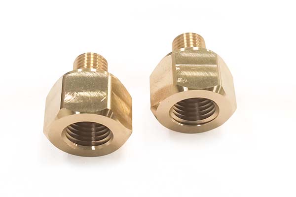
- Brass: Brass is a copper - zinc alloy that is relatively soft and easy to machine. It is often used for decorative parts, fittings, and electrical components.
- Plastic: Plastic materials vary widely in their properties. Some plastics, like acrylic, are easy to machine and can be cut with sharp tools at moderate speeds. Others, such as engineering plastics like PEEK, require more careful machining due to their high strength and heat resistance. Yigu Technology, as a plastic metal parts custom manufacturing Supplier, understands the importance of selecting the right tools and parameters when working with plastic materials. Different plastics respond differently to cutting speeds and feeds, and Yigu Technology's experience allows them to optimize the process for each specific plastic, ensuring high - quality parts with minimal defects.
- Composite Materials: Composite materials, made up of two or more different materials, can be challenging to machine. The combination of different properties in composites requires careful selection of cutting tools and parameters to avoid delamination and other defects.
2.3 Tool Geometry
- Tool Diameter: The diameter of the cutting tool affects the cutting speed and feed rate. Larger - diameter tools generally require lower spindle speeds to maintain the same cutting speed. For example, if you double the diameter of a cutting tool, the spindle speed needs to be halved to keep the cutting speed constant.
- Tool Length: The length of the tool can impact its rigidity. Longer tools are more prone to deflection, which can affect the accuracy of the cut. In some cases, shorter tools may be preferred for high - precision machining.
- Flute Count: The number of flutes on a cutting tool affects the chip - evacuation ability and the feed rate. Tools with more flutes can generally handle higher feed rates but may be more prone to chip clogging in some materials.
- Tool Coating: Tool coatings, such as titanium nitride (TiN), titanium aluminum nitride (TiAlN), and diamond - like carbon (DLC), can improve the performance and lifespan of cutting tools. These coatings reduce friction, increase wear resistance, and can withstand higher cutting temperatures.
2.4 Tool Wear
Tool wear is a natural phenomenon in CNC machining. As the cutting tool removes material from the workpiece, its cutting edges gradually wear down. The rate of tool wear depends on factors such as the cutting speed, feed rate, depth of cut, workpiece material, and tool material. Excessive tool wear can lead to poor surface finish, inaccurate cuts, and increased tool replacement costs. Regular monitoring of tool wear and timely replacement of worn - out tools are essential for maintaining the quality and efficiency of the machining process.
3. CNC Machine Parameters
3.1 Machine Capabilities
- Machine Power: The power of the CNC machine determines its ability to drive the cutting tool at high speeds and feed rates. A more powerful machine can handle larger cutting forces and is suitable for machining harder materials or removing large amounts of material.
- Machine Torque: Torque is the rotational force that the machine can apply to the spindle. It is important for applications where high - torque is required, such as drilling deep holes or milling large - diameter cutters.
- Machine Spindle Limits: The spindle of the CNC machine has limits on its maximum speed and torque. Operating the spindle beyond these limits can cause damage to the machine and affect the machining accuracy.
- Machine Feed Rate Limits: The machine also has limits on the maximum feed rate that it can achieve. Exceeding these limits may result in poor surface finish, tool breakage, or inaccurate cuts.
3.2 Machine Accuracy
Machine accuracy is crucial for producing high - quality parts. Factors that affect machine accuracy include the quality of the machine's mechanical components, such as the guideways and ball screws, and the accuracy of the CNC control system. Regular calibration and maintenance of the machine are necessary to ensure its accuracy over time.
3.3 Machine Rigidity
Machine rigidity determines how well the machine can resist cutting forces without deflecting. A rigid machine is essential for achieving accurate cuts and good surface finish, especially when machining at high speeds or with large cutting forces. The design and construction of the machine, as well as the installation and alignment of its components, play a significant role in its rigidity.
3.4 Tool Holder Type and Collet Size
The type of tool holder and the size of the collet used to hold the cutting tool can affect the accuracy and stability of the cutting process. Different tool holder types, such as ER collets, BT tool holders, and HSK tool holders, have different clamping forces and accuracy levels. The collet size should be selected to match the diameter of the cutting tool to ensure a secure and accurate hold.
3.5 Machine Software and CNC Control System
The machine software and CNC control system are responsible for controlling the movement of the machine axes, the spindle speed, and the feed rate. Modern CNC control systems offer advanced features such as high - speed machining, adaptive control, and real - time monitoring. The software should be regularly updated to ensure compatibility with the latest hardware and to take advantage of new features and improvements.
4. Cutting Conditions Optimization
4.1 Optimal Cutting Speed
Determining the optimal cutting speed is a balance between maximizing the material removal rate and minimizing tool wear. For different workpiece - tool material combinations, there is an ideal cutting speed range. For example, when machining aluminum with a carbide end mill, the optimal cutting speed may be in the range of 200 - 500 m/min, while for machining stainless steel with the same tool, the optimal speed may be around 80 - 150 m/min.
4.2 Optimal Feed Rate
The optimal feed rate depends on factors such as the cutting speed, the tool geometry, and the workpiece material. A higher feed rate can increase the material removal rate but may also lead to increased tool wear and a rougher surface finish. For finishing operations, a lower feed rate is often used to achieve a better surface finish.
4.3 Optimal Depth of Cut
The depth of cut affects the cutting forces and the material removal rate. A deeper cut can remove more material in a single pass but may also require more power and increase the risk of tool breakage. In rough machining, a larger depth of cut can be used to quickly remove most of the material, while in finishing, a smaller depth of cut is applied to achieve the desired surface finish and dimensional accuracy.
4.4 Optimal Width of Cut
The width of cut is relevant in operations such as milling. It should be carefully selected based on the tool diameter, the cutting speed, and the feed rate. A wider cut may require more power and can affect the tool life and the surface finish.
4.5 Tool Life Optimization
To optimize tool life, it is important to select the right cutting tool for the job, use appropriate cutting parameters, and ensure proper cooling and lubrication. Tool life can be extended by reducing the cutting speed and feed rate, but this may also reduce the machining efficiency. Therefore, a balance needs to be struck between tool life and productivity.
4.6 Surface Finish Optimization
A good surface finish is often required in CNC machining, especially for parts that will be used in applications where appearance or functionality depends on it. To optimize the surface finish, factors such as the cutting speed, feed rate, depth of cut, tool geometry, and tool wear need to be carefully controlled. For example, using a lower feed rate and a sharp cutting tool can result in a smoother surface finish.
4.7 Material Removal Rate (MRR)
The material removal rate is the volume of material removed per unit time. It is calculated by multiplying the feed rate, the depth of cut, and the width of cut. Increasing the MRR can improve the machining efficiency, but it should be done within the limits of the machine capabilities and the tool's ability to withstand the cutting forces.
4.8 Cutting Force and Cutting Temperature
Cutting force and cutting temperature are important factors that affect the machining process. High cutting forces can cause tool deflection, vibration, and premature tool wear. Cutting temperature can also impact the tool life and the quality of the machined surface. Using proper cutting parameters, coolant, and tool coatings can help in reducing cutting force and temperature.
4.9 Coolant Usage
Coolant plays a crucial role in CNC machining. It helps in reducing cutting temperature, lubricating the cutting tool, and flushing away chips. Different types of coolants, such as water - soluble coolants, oil - based coolants, and synthetic coolants, are available, and the choice depends on the workpiece material, the cutting tool material, and the machining operation.
4.10 Tool Deflection and Vibration Control
Tool deflection and vibration can lead to inaccurate cuts and poor surface finish. To control tool deflection, factors such as tool length, diameter, and rigidity should be considered. Vibration can be minimized by using proper cutting parameters, balancing the cutting tool, and ensuring the machine is properly tuned.
5. Calculator Features and Usage
5.1 User Interface
CNC cutting speed calculators come with user - friendly interfaces that allow operators to easily input the required parameters. The interface typically includes fields for entering the tool diameter, spindle speed, feed rate, chip load per tooth, and workpiece and tool materials. Some calculators also provide dropdown menus or selection boxes for quickly choosing common values.
5.2 Input Parameters
As mentioned earlier, the input parameters for a cutting speed calculator include information about the cutting tool (diameter, number of teeth, material), the workpiece (material), and the desired cutting conditions (cutting speed, feed rate, depth of cut). These parameters are used by the calculator to perform the necessary calculations.
5.3 Output Results
The calculator provides output results such as the calculated cutting speed, spindle speed, feed rate, and other relevant parameters. Some calculators may also display additional information such as the estimated tool life, the material removal rate, and recommendations for optimal cutting conditions.
5.4 Mobile App, Desktop Software, and Online Calculator
CNC cutting speed calculators are available in different formats. Mobile apps allow operators to access the calculator on - the - go, which is convenient for those working in the shop floor. Desktop software may offer more advanced features and the ability to save and manage machining data. Online calculators can be accessed from any device with an internet connection and are often free to use.
5.5 Units Conversion
Most cutting speed calculators support units conversion, allowing users to input and receive results in different units such as metric (millimeters, meters per minute) or imperial (inches, surface feet per minute). This is useful for users who may be accustomed to different unit systems.
5.6 Customizable Settings
Some calculators offer customizable settings, such as the ability to adjust the safety factors used in the calculations or to define specific tool or material properties. This allows users to tailor the calculator to their specific machining requirements.
5.7 Database of Materials and Tools
Cutting speed calculators often come with a built - in database of common workpiece materials and cutting tools. This database contains pre - defined values for properties such as hardness, thermal conductivity, and recommended cutting parameters. Users can simply select the material and tool from the database, and the calculator will use the appropriate values for the calculations.
5.8 Real - Time Calculation
Modern cutting speed calculators perform real - time calculations, meaning that as soon as the user enters or changes an input parameter, the results are immediately updated. This provides instant feedback and allows users to quickly explore different cutting scenarios.
5.9 Error Messages and Help and Support
Calculators also provide error messages when incorrect or inconsistent input is provided. Additionally, they often offer help and support features, such as user manuals, FAQs, or online tutorials, to assist users in using the calculator effectively.
FAQs
- What is the most important factor in CNC cutting speed calculation?
- The most important factor is the combination of workpiece and tool materials. Different materials have different properties, and this significantly affects the optimal cutting speed. For example, hard materials like tungsten carbide require lower cutting speeds compared to softer materials like aluminum when using the same type of cutting tool.
- How can I extend the life of my cutting tools?
- You can extend tool life by using the correct cutting parameters, such as appropriate cutting speed, feed rate, and depth of cut. Using a suitable coolant to reduce cutting temperature and friction also helps. Additionally, choosing the right cutting tool material for the workpiece and regularly maintaining and sharpening the tools can increase their lifespan.
- **Can I
