Introduction
The mold opens. The finished part should drop out cleanly. Instead, it sticks. Ejector pins push harder. The part deforms. Production stops while someone pries it loose.
This scenario plays out daily in molding shops around the world. The culprit? Poorly designed ejector systems —specifically, miscalculated ejector stroke .
Ejector stroke is the distance ejector pins travel to push a finished part from the mold. Get it right, and parts eject cleanly, cycle after cycle. Get it wrong, and you face stuck parts, deformed components, and costly downtime.
This guide explores ejector stroke injection molding from the perspective of mold designers and manufacturers. We’ll cover how ejector systems work, design principles, common pitfalls, and how to ensure reliable part ejection.
What Is Ejector Stroke in Injection Molding?
The Role of Ejection
After plastic fills the mold and cools, the part must be removed. The ejector system accomplishes this. Ejector pins—steel rods that move forward—push the part out of the mold cavity.
Ejector stroke is the distance these pins travel from their retracted position to full extension. It must be sufficient to clear the part from the mold entirely.
If the stroke is too short, the part remains partially in the cavity. If it’s too long, pins may over-travel, potentially damaging the part or mold components.
Basic Injection Molding Process Recap
To understand ejection, recall the full injection molding cycle:
| Step | Description |
|---|---|
| Material preparation | Pellets selected and dried |
| Heating and melting | Pellets melt in heated barrel (150–350°C) |
| Injection | Molten plastic injected at 50–200 MPa pressure |
| Cooling | Part solidifies; coolant circulates through mold |
| Mold opening | Mold halves separate |
| Ejection | Ejector pins push part out |
| Part removal | Part clears mold; cycle repeats |
Ejection occurs after mold opening. The timing and stroke length are critical.
What Are the Key Components of an Ejector System?
Ejector Pins
The most common ejection component. Round pins are standard due to ease of manufacturing. Flat or rectangular pins serve narrow slots or channels where round pins won’t fit.
Pin size matters:
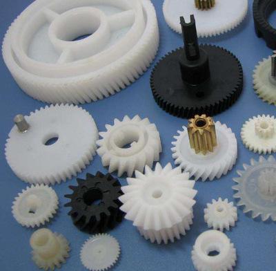
- 1–2 mm diameter : Small, delicate parts like tiny gears
- Larger diameters : Robust parts requiring more ejection force
Ejector Plate
Ejector pins mount to an ejector plate . The injection molding machine’s ejector mechanism pushes this plate forward. All pins move together, distributing force across the part.
Return Pins
Also called reset pins . As the mold closes, these pins push the ejector plate back to its retracted position. This ensures pins don’t crash into the mold cavity during the next cycle.
Ejector Stroke Limiters
Physical stops that prevent over-travel. They ensure the ejector plate moves exactly the designed distance—no more, no less.
What Design Principles Ensure Reliable Ejection?
Even Distribution of Ejector Pins
Pins must be evenly distributed across the part. Concentrating pins on one side creates uneven forces. The part may tilt during ejection, causing deformation or sticking.
A study found that evenly distributing pins in a flat 100mm x 50mm part reduced ejection-induced deformation by 30% compared to uneven distribution.
Proper Pin Size and Shape Selection
| Part Type | Recommended Pin |
|---|---|
| Small, delicate (e.g., 10mm gear) | 1–2 mm diameter round pins |
| Medium parts | 3–5 mm diameter round pins |
| Large, robust parts | 6–12 mm diameter round pins |
| Parts with narrow slots | Flat or rectangular pins |
Strategic Pin Placement
Place pins at strategic locations based on part geometry:
- Near thick sections where shrinkage creates higher retention force
- Adjacent to ribs or bosses that resist ejection
- Away from cosmetic surfaces where pin marks would be visible
Simulation software like Moldflow analyzes ejection stress. It predicts high-retention areas and suggests optimal pin locations before the mold is built.
Sufficient Stroke Length
Calculate required stroke as:
Part height + clearance + safety margin
For a part 50 mm tall, with 5 mm clearance and 5 mm safety margin, required stroke is 60 mm .
If the part has undercuts or side actions, ejection may occur in stages. Some molds use a two-stage ejector system —short stroke to disengage side actions, then full stroke to eject.
What Common Design Pitfalls Should You Avoid?
Incorrect Pin Placement
Placing pins too close to edges or thin walls causes deformation. A pin near a thin-walled container section can bulge or crack the wall.
Solution : Use simulation software to analyze ejection stress. Add support structures or reinforce areas around pins if needed.
Uneven Ejection Forces
Uneven forces occur when:
- Pin lengths vary
- Mold material stiffness differs around pins
- Ejector mechanism is misaligned
Solution : Maintain all pin lengths within ±0.05 mm tolerance. Use consistent mold materials. Regularly calibrate the machine’s ejector mechanism.
Inadequate Venting
Trapped air between the part and mold creates vacuum. This makes ejection difficult, even with properly designed pins.
Solution : Add vent holes 0.1–0.3 mm in diameter near ejector pins. Use vented ejector pins with grooves along their length to allow air escape.
Insufficient Stroke
Short stroke leaves part partially in cavity. Operators may pry parts out—damaging both part and mold.
Solution : Calculate stroke carefully. Add safety margin. Test during mold sampling.
Excessive Stroke
Over-travel can bend pins or damage the ejector plate. Pins may crash into the mold’s B side.
Solution : Install stroke limiters . Verify travel during setup.
What Role Does Mold Material Play?
Ejector pins slide against mold steel thousands or millions of times. Material selection affects wear and reliability.
| Mold Component | Recommended Material | Why |
|---|---|---|
| Mold base | P20 steel | Good machinability; stable |
| Cavity/core (high volume) | H13 steel | Heat-resistant; wear-resistant |
| Ejector pins | Hardened steel (58–62 HRC) | Wear resistance; strength |
| Ejector plate | P20 or 4140 steel | Rigidity; dimensional stability |
Softer mold materials wear faster around ejector pins. Over time, pin holes enlarge, allowing flash. Harder materials maintain precision longer.
How Do You Troubleshoot Ejection Problems?
| Problem | Likely Cause | Solution |
|---|---|---|
| Part sticks | Insufficient stroke; inadequate venting | Increase stroke; add vents |
| Part deforms | Uneven pin distribution; pins too small | Redistribute pins; use larger pins |
| Pin marks visible | Pins on cosmetic surfaces | Relocate pins to non-cosmetic areas |
| Pin breakage | Excessive force; misalignment | Reduce ejection force; realign system |
| Flash around pins | Worn pin holes; excessive clearance | Replace worn mold components |
| Part ejects at angle | Uneven pin lengths | Grind pins to uniform length |
A Troubleshooting Case Study
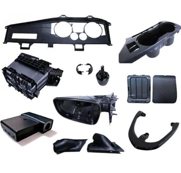
A manufacturer produced automotive interior trim parts. Parts ejected with visible deformation along one edge. The mold had been running for 100,000 cycles without issues.
Inspection revealed uneven pin lengths. Three pins had worn shorter than others due to localized wear in the ejector plate. The shorter pins provided less force on one side, causing the part to tilt during ejection.
Solution: Replace worn pins and regrind the ejector plate surface to ensure all pins seated evenly. Deformation disappeared.
What Advanced Ejection Techniques Exist?
Two-Stage Ejection
Some parts require sequential ejection. A short stroke disengages side actions or unscrewing mechanisms. A second stroke fully ejects the part.
Air-Assisted Ejection
Compressed air blows between part and mold, breaking vacuum. This reduces required ejection force—useful for large, flat parts prone to sticking.
Stripper Plates
For large, flat parts, a stripper plate replaces ejector pins. The plate contacts the entire part surface, pushing evenly. This eliminates pin marks and distributes force uniformly.
Hydraulic Ejection
Some large molds use hydraulic cylinders instead of mechanical ejector pins. This allows independent control of ejection force and timing.
Yigu Technology's Perspective
At Yigu Technology , we design and build molds for our own production. Ejection reliability is not theoretical—it’s a daily requirement. A stuck part stops production. Every minute of downtime costs money.
Our mold designers use Moldflow simulation to analyze ejection stress and optimize pin placement before machining begins. We specify hardened steel pins and maintain tight tolerances on pin lengths and hole diameters.
We incorporate vented pins for parts prone to sticking. For large, flat components, we use stripper plates to ensure even ejection without visible pin marks.
We also believe in testing before shipping. Every mold undergoes sample runs. We verify ejector stroke, pin distribution, and part release before the mold leaves our facility.
Conclusion
Ejector stroke may seem like a small detail in injection molding. But it determines whether parts eject cleanly—or stick, deform, and stop production.
Proper design means:
- Even pin distribution across the part
- Correct pin size for the application
- Strategic placement away from cosmetic surfaces
- Sufficient stroke length with safety margin
- Adequate venting to prevent vacuum lock
Mold designers who master these principles deliver tools that run reliably for millions of cycles. Those who ignore them build molds that frustrate operators and delay production.
Ejection is the last step in the molding cycle. But it’s the step that makes the next cycle possible. Get it right, and production runs smoothly. Get it wrong, and nothing else matters.
FAQ
What factors determine required ejector stroke?
Part size and shape are primary factors. Taller parts need longer stroke. Parts with deep cavities or undercuts may require staged ejection. Mold structure matters—side actions or unscrewing mechanisms may need initial short stroke to disengage, followed by full ejection. Part thickness also influences ejection force requirements, which can relate to stroke design.
How do you ensure even ejection forces?
Even pin distribution is essential. Use simulation software to analyze ejection stress and optimize pin placement. Maintain pin length tolerance within ±0.05 mm . Use consistent mold materials and regularly calibrate the machine’s ejector mechanism. For large, flat parts, consider stripper plates instead of individual pins.
What causes parts to stick in the mold?
Common causes: insufficient ejector stroke (part not fully cleared), inadequate venting (vacuum holds part against mold), excessive shrinkage (part grips core tightly), surface finish too smooth (part adheres), or ejection forces uneven (part tilts). Solutions include increasing stroke, adding vents, adjusting cooling, and optimizing pin layout.
How do you prevent ejector pin marks on cosmetic surfaces?
Place pins away from visible surfaces. Use smaller pins in non-cosmetic areas. For parts requiring pristine surfaces, use stripper plates that contact the entire part face, distributing force without creating individual pin marks. Some applications use air ejection to avoid physical contact entirely.
What maintenance does an ejector system require?
Regularly inspect pins for wear . Measure pin lengths to ensure uniformity. Clean pins and pin holes to prevent debris buildup. Lubricate moving components appropriately. Check ejector plate alignment and stroke limiters . Replace worn pins before they cause flash or uneven ejection. For high-volume production, schedule preventive maintenance based on cycle count.
Contact Yigu Technology for Custom Manufacturing
At Yigu Technology , we design and build precision molds with reliable ejection systems. Our team uses simulation software to optimize pin placement and stroke length before machining. We specify hardened steel components and maintain tight tolerances to ensure millions of trouble-free cycles. Whether you need a new mold or support with an existing tool, contact us today to discuss your injection molding project.