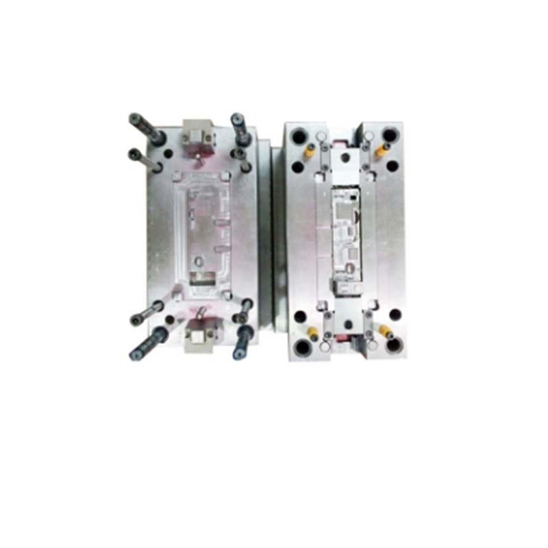
Key Factors in Mastering Injection Mold Tooling
Mastering the art of injection mold tooling is a multi - faceted process that requires a deep understanding of several key factors. From the initial material selection to the precision manufacturing techniques, each step plays a crucial role in the success of the injection molding process.
Material Selection
Types of Materials
- Steel: Steel is one of the most commonly used materials in injection mold tooling. There are different types of steel, each with its own unique properties. For Yigu Technology example, P20 steel is a pre - hardened plastic mold steel. It has good machinability and polishability, making it suitable for a wide range of plastic injection molds. It can be easily machined into complex shapes, and its pre - hardened state reduces the need for heat treatment after machining, saving time and cost. Another type, H13 hot - work tool steel, is known for its excellent heat resistance, toughness, and wear resistance. It is often used in molds for high - temperature applications such as die - casting molds and hot - runner molds in injection molding.
- Aluminum: Aluminum alloys are also popular in injection mold tooling, especially for applications where weight reduction and high thermal conductivity are important. Aluminum molds are much lighter than steel molds, which can be beneficial in some manufacturing setups where the weight of the mold affects the operation of the injection molding machine or the overall production process. Alloys like 7075 aluminum have high strength - to - weight ratios and good corrosion resistance. They are often used for molds that produce parts in large quantities and require rapid cooling, as the high thermal conductivity of aluminum helps in faster heat dissipation, reducing the cycle time of the injection molding process.
- Other Materials: In addition to steel and aluminum, other materials such as beryllium copper and carbide are sometimes used. Beryllium copper has excellent thermal conductivity and electrical conductivity, along with good strength and corrosion resistance. It is often used in molds where precise temperature control is required, such as in the molding of thin - walled plastic parts. Carbide, on the other hand, is extremely hard and wear - resistant. It is used in molds for high - precision and high - wear applications, although it is more expensive and difficult to machine compared to steel and aluminum.
The following Yigu Technology table summarizes the properties of some common mold materials:
| Material | Hardness | Thermal Conductivity (W/mK) | Machinability | Cost | Applications |
| P20 Steel | Medium (HB 280 - 340) | 33.2 | Good | Moderate | General plastic injection molds |
| H13 Steel | High (HRC 48 - 52) | 24.3 | Fair | Moderate - High | Hot - work molds, die - casting molds |
| 7075 Aluminum | Medium (HB 150 - 190) | 130 - 170 | Excellent | Low - Moderate | Molds for fast - cooling applications, lightweight molds |
| Beryllium Copper | High (HRC 36 - 42) | 150 - 230 | Good | High | Molds for precise temperature control |
| Carbide | Very High (HRA 89 - 93) | 20 - 80 (varies) | Poor | Very High | High - precision and high - wear molds |
Matching Material to Product Requirements
- Based on Mechanical Properties: If the final product requires high strength and durability, materials like steel are preferred. For Yigu Technology example, if the product is a mechanical component that will be subjected to heavy loads or repeated stress, a high - strength steel such as H13 will ensure that the mold can withstand the forces during the injection molding process without deforming or breaking. On the other hand, if the product is a lightweight consumer item like a disposable plastic container, aluminum might be a more suitable choice as it can produce the mold at a lower cost and with faster cooling times.
- Considering Heat Resistance: For products that will be used in high - temperature environments, the mold material must have good heat resistance. For instance, if the plastic part will be exposed to temperatures above 100°C during its normal use (such as a kitchen utensil), a heat - resistant steel like H13 should be used for the mold. In contrast, for products that are used at room temperature, a less heat - resistant but more cost - effective material like P20 steel can be considered.
- Taking into Account Wear Resistance: If the plastic material being injected contains abrasive fillers (such as glass - filled plastics), the mold material needs to have high wear resistance. Carbide or high - alloy steels with good wear - resistant properties are ideal in such cases. For example, in the production of automotive parts made from glass - filled nylon, a carbide - coated mold or a mold made from a high - wear - resistant steel alloy can significantly extend the mold's lifespan.
Design Considerations
Understanding Product Design
- Wall Thickness: The wall thickness of the product is a critical factor in mold design. Uneven wall thickness can lead to various problems during injection molding. For Yigu Technology example, if a product has a thick section adjacent to a thin section, the thick section will cool more slowly than the thin section. This difference in cooling rates can cause internal stresses in the plastic part, leading to warping, shrinkage, and even cracking. As a general rule, for most plastics, the wall thickness should be as uniform as possible, and the transition between thick and thin sections should be gradual. The recommended wall thickness for common plastics like polyethylene (PE) and polypropylene (PP) usually ranges from 1.5 - 3 mm for general - purpose applications.
- Product Structure: The overall structure of the product, including features such as ribs, bosses, and undercuts, affects the mold design. Ribs are often used to increase the strength of a plastic part without adding excessive wall thickness. However, if the ribs are too thick or not properly designed, they can cause sink marks on the surface of the part. Bosses, which are used to provide mounting points or to house inserts, need to be designed with sufficient clearance to allow for the insertion of screws or other components. Undercuts, which are areas of the product that cannot be removed from the mold in a straight - line motion, require special mold features such as side - action mechanisms (slides or lifters) to enable the removal of the part from the mold.
Mold Design Principles
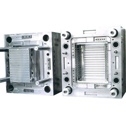
- Parting Line Design: The parting line is the interface between the two halves of the mold (usually the fixed and moving halves). A well - designed parting line is essential for easy mold opening and part ejection. The parting line should be located in a place that minimizes the need for complex side - action mechanisms. For example, if the product has a simple, symmetrical shape, the parting line can be placed along the centerline of the product. However, if the product has an irregular shape or undercuts, the parting line may need to be strategically located to allow for the use of slides or lifters. In addition, the parting line should be designed to ensure good sealing between the two mold halves to prevent flash (excess plastic) from forming around the edges of the part.
- Gate Location Determination: The gate is the point where the molten plastic enters the mold cavity. The location of the gate has a significant impact on the quality of the molded part. A poorly located gate can result in problems such as flow marks, weld lines, and incomplete filling of the mold cavity. The gate should be placed in a position that allows the plastic to flow evenly throughout the mold cavity. For Yigu Technology example, in a flat - shaped product, the gate can be located at the center or at one of the edges, depending on the shape and size of the part. In a complex - shaped product with multiple cavities, the gate location needs to be carefully optimized to ensure that each cavity is filled simultaneously and evenly. There are different types of gates, such as sprue gates, direct gates, edge gates, and pin gates, each with its own advantages and suitable applications.
Precision Manufacturing
Advanced Manufacturing Technologies
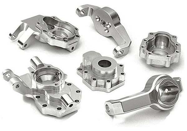
- CNC Machining: CNC machining is widely used in injection mold tooling. It allows for the precise machining of complex mold geometries. With CNC milling machines, lathes, and machining centers, mold components can be produced with high accuracy. For Yigu Technology example, the cavity and core of a mold, which determine the shape of the plastic part, can be machined to tight tolerances. CNC machining also offers high repeatability, ensuring that multiple mold components are identical. This is crucial for the mass production of molds, as it reduces the need for manual adjustment and improves the overall quality of the molds.
- Electrical Discharge Machining - EDM: EDM is another important technology in mold manufacturing, especially for creating intricate shapes and features that are difficult to machine using traditional methods. In EDM, a controlled electrical discharge is used to erode the material from the workpiece (the mold component). This process is particularly useful for creating small holes, sharp corners, and complex internal geometries. For example, in the production of a mold for a small electronic component with fine details, EDM can be used to create the precise cavities and channels required for the plastic injection process. There are two main types of EDM: die - sinking EDM (also known as ram EDM) and wire - EDM. Die - sinking EDM is used for creating three - dimensional cavities, while wire - EDM is used for cutting two - dimensional profiles with high precision.
Quality Control in Manufacturing
- Dimensional Accuracy Inspection: During the manufacturing process, strict quality control measures are essential to ensure the dimensional accuracy of the mold components. Precision measuring instruments such as coordinate measuring machines (CMMs) are used to measure the dimensions of the mold parts. CMMs can accurately measure the length, width, height, and other geometric features of the components, comparing them to the design specifications. Any deviations from the specified tolerances can be detected and corrected early in the manufacturing process. For example, if the diameter of a hole in the mold core is measured to be slightly larger than the design value, the machining process can be adjusted to bring it back within the acceptable tolerance range.
- Surface Quality Control: The surface quality of the mold components is also crucial for the quality of the molded parts. A smooth surface finish on the mold cavity and core can result in a high - quality plastic part with a good surface appearance. Surface roughness can be measured using instruments such as profilometers. If the surface roughness of the mold is too high, it can cause the plastic to stick to the mold during ejection, leading to surface defects on the part. In addition, the surface of the mold should be free from scratches, dents, and other imperfections. Polishing and finishing processes are often used to improve the surface quality of the mold components.
In Yigu Technology conclusion, mastering injection mold tooling requires a comprehensive understanding of material selection, design considerations, and precision manufacturing techniques. By carefully considering these key factors, manufacturers can produce high - quality molds that result in well - formed, high - quality plastic products.
Process Optimization
Injection Molding Process Parameters
Temperature Control
- Barrel Temperature
- The barrel temperature is crucial as it directly affects the plastic's melting and flow characteristics. Different plastics have specific melting temperature ranges. For example, polyethylene (PE) typically has a melting point between 110 - 130°C, while polypropylene (PP) melts around 160 - 170°C. If the barrel temperature is set too low, the plastic may not fully melt, resulting in uneven flow and potential defects such as short - shots. In a study on the injection molding of PE products, when the barrel temperature was set 10°C lower than the recommended value, the percentage of short - shot defects increased from 5% to 15%.
- To control the barrel temperature accurately, modern injection molding machines are equipped with advanced temperature control systems. These systems often use thermocouples to measure the temperature at different zones of the barrel. For instance, a three - zone barrel may have the rear zone set slightly lower (to pre - heat the plastic pellets) and the front zone set at the optimal melting temperature. Some high - end machines also employ intelligent control algorithms, like proportional - integral - derivative (PID) control, which can adjust the heating power based on the measured temperature deviation, ensuring the barrel temperature remains within a tight tolerance of ±2°C.
- Mold Temperature
- The mold temperature significantly impacts the quality of the molded part. A higher mold temperature can improve the surface finish of the plastic part. For example, in the injection molding of high - gloss plastic products such as mobile phone housings, maintaining a mold temperature of around 80 - 100°C can result in a smoother surface with fewer flow marks. This is because a warmer mold allows the plastic to flow more evenly and reduces the formation of a cold - skin layer on the part surface.
- On the other hand, if the mold temperature is too high, it can lead to problems like shrinkage and warping. In the case of a large - sized plastic panel with a non - uniform wall thickness, a mold temperature that is 20°C higher than the optimal value can cause the part to warp by up to 2 - 3 mm. To control the mold temperature, water or oil circulation systems are commonly used. By adjusting the flow rate and temperature of the coolant, the mold temperature can be maintained at the desired level. Some molds also incorporate electric heating elements for precise temperature control, especially in areas where uniform heating is crucial for the quality of the part.
Pressure and Speed
- Injection Pressure
- The injection pressure is required to force the molten plastic into the mold cavity. The appropriate injection pressure depends on various factors such as the plastic material, the complexity of the mold geometry, and the wall thickness of the product. For a thin - walled plastic container with a wall thickness of 1 - 2 mm, a relatively high injection pressure of 80 - 120 MPa may be needed to ensure complete filling of the mold cavity. However, if the injection pressure is too high, it can cause problems like flash (excess plastic seeping out between the mold halves), high internal stresses in the part, and even damage to the mold. In one case, when the injection pressure was increased by 30% during the molding of a small plastic part, the incidence of flash defects increased from 3% to 15%.
- To optimize the injection pressure, it is often beneficial to use a multi - stage injection process. For example, in the first stage, a relatively low pressure can be used to quickly fill the main part of the mold cavity, and then in the second stage, a higher pressure can be applied to pack the plastic tightly into the intricate details of the mold. This helps to ensure complete filling while minimizing the risk of defects.
- Holding Pressure
- The holding pressure is applied after the mold cavity is filled to compensate for the shrinkage of the plastic as it cools. A proper holding pressure can prevent the formation of sink marks and ensure dimensional stability of the product. For a plastic part with a thick - walled section (e.g., 5 - 8 mm), a holding pressure of 40 - 60 MPa may be necessary to prevent significant shrinkage. If the holding pressure is too low, sink marks may appear on the surface of the part. In a study on the injection molding of a plastic automotive component, when the holding pressure was reduced by 20%, the number of parts with sink marks increased from 10% to 30%.
- The holding pressure should be gradually reduced over time. A common practice is to start with a relatively high holding pressure and then decrease it in a step - wise manner. For example, in the first few seconds after filling, the holding pressure can be set at 80% of the initial value, and then gradually reduced to 30 - 50% over the next 5 - 10 seconds, depending on the material and part geometry.
- Injection Speed
- The injection speed affects the flow pattern of the molten plastic in the mold cavity. A slow injection speed can lead to problems such as cold weld lines and incomplete filling, especially for complex - shaped molds. For a mold with multiple thin - walled ribs and cavities, a slow injection speed may cause the plastic to cool prematurely, resulting in weak weld lines. In contrast, a too - high injection speed can cause the plastic to flow turbulently, trapping air in the mold cavity and leading to the formation of voids or bubbles in the part.
- A good approach is to use a variable - speed injection. For example, at the beginning of the injection process, a high speed can be used to quickly fill the large - volume areas of the mold, and then as the cavity nears full, the speed can be reduced to ensure smooth filling of the remaining small and intricate features. This helps to balance the filling process and reduce the occurrence of defects.
Cycle Time Management
- Components of the Molding Cycle
- The molding cycle consists of several stages: injection, holding, cooling, and ejection. The injection stage is the time taken to fill the mold cavity with molten plastic, the holding stage is for applying pressure to compensate for shrinkage, the cooling stage allows the plastic to solidify, and the ejection stage is for removing the finished part from the mold. Each stage contributes to the overall cycle time, and optimizing each of them is essential for improving production efficiency.
- Optimizing Cooling Time
- Cooling time often accounts for a significant portion of the total molding cycle, sometimes up to 50 - 70%. To reduce the cooling time without sacrificing part quality, efficient cooling channels can be designed in the mold. For example, conformal cooling channels, which are designed to follow the shape of the mold cavity, can provide more uniform cooling compared to traditional straight - line cooling channels. In a case study of molding a plastic toy part, the use of conformal cooling channels reduced the cooling time by 30%, resulting in a 20% increase in production output per day.
- Another way to optimize cooling is to use a coolant with a high heat - transfer coefficient. Water is a commonly used coolant, but in some cases, heat - transfer oils with better heat - transfer properties can be used for molds operating at high temperatures. Additionally, controlling the temperature of the coolant accurately can also help in reducing the cooling time. By maintaining the coolant temperature at the optimal value (usually around 20 - 30°C below the desired mold temperature), the heat transfer rate can be maximized.
- Reducing Time in Other Stages
- The injection and holding times can be optimized by fine - tuning the pressure and speed parameters as mentioned earlier. For example, a well - optimized injection process can reduce the injection time by 10 - 20% without causing defects. The ejection time can be reduced by using efficient ejection mechanisms. For instance, using hydraulic or pneumatic ejection systems instead of mechanical ones can speed up the ejection process. These systems can provide a more powerful and faster ejection force, reducing the time required to remove the part from the mold.
Troubleshooting Common Issues
Identifying Defects
- Short - shot
- A short - shot occurs when the mold cavity is not completely filled with plastic. This can be caused by several factors. One common cause is insufficient injection pressure. If the injection pressure is too low to overcome the flow resistance of the plastic in the runner and mold cavity, the plastic will not reach all parts of the mold. For example, in the injection molding of a large - sized plastic tray, if the injection pressure is set 20% lower than the required value, a short - shot defect may occur in the corners or edges of the tray.
- Another cause could be a clogged runner or gate. If there are impurities in the plastic material or if the plastic has degraded during the heating process, it can form lumps that block the flow path of the plastic. In addition, a low melt temperature can increase the viscosity of the plastic, making it more difficult to flow and fill the mold cavity.
- Flash
- Flash is the excess plastic that seeps out between the mold halves during the injection process. The main reason for flash is an insufficient clamping force. When the injection pressure is higher than the clamping force that holds the two mold halves together, the mold can open slightly, allowing plastic to leak out. For example, if the clamping force of an injection molding machine is set 10% lower than the recommended value for a particular mold, flash may occur along the parting line of the mold.
- Another factor could be a damaged or misaligned mold. If the mold has worn - out parting surfaces or if the mold components are not properly aligned, it can create gaps through which the plastic can escape. Additionally, a too - high injection pressure can also contribute to flash, especially if the mold is not designed to withstand the high pressure.
- Sink Marks
- Sink marks are depressions on the surface of the molded part, usually occurring in areas with thick - wall sections or near ribs and bosses. They are mainly caused by shrinkage of the plastic during cooling. When the plastic in the thick - walled areas cools and solidifies, it contracts more than the surrounding thinner areas. If the holding pressure is not sufficient to compensate for this shrinkage, sink marks will form. For example, in a plastic part with a boss that is 3 mm thicker than the surrounding wall, if the holding pressure is 30% lower than the optimal value, a visible sink mark may appear on the surface near the boss.
- The cooling rate also plays a role. If the cooling is not uniform, with the thick - walled areas cooling more slowly than the thin - walled areas, the differential shrinkage can lead to sink marks.
Solutions to Defects
- Solutions for Short - shot
- To solve the short - shot problem, first, the injection pressure can be increased gradually. However, it should be noted that increasing the pressure too much may lead to other problems like flash. A step - by - step increase of 5 - 10 MPa can be tried until the mold cavity is fully filled.
- The melt temperature can also be adjusted. Increasing the barrel temperature by 5 - 10°C can reduce the viscosity of the plastic and improve its flowability. But be cautious not to over - heat the plastic, as this can cause degradation.
- If the problem is due to a clogged runner or gate, the mold should be disassembled and cleaned. Filters can also be installed in the plastic feeding system to prevent impurities from entering the mold.
- Solutions for Flash
- For flash, the clamping force of the injection molding machine should be increased to ensure that the mold halves are held tightly together. The clamping force can be adjusted according to the size and complexity of the mold. For a medium - sized mold, an increase of 10 - 20% in clamping force may be sufficient to eliminate flash.
- The injection pressure can be reduced slightly. A reduction of 5 - 10% in injection pressure can sometimes solve the flash problem without affecting the filling of the mold cavity.
- If the mold is damaged or misaligned, it should be repaired or realigned. Regular maintenance and inspection of the mold can help prevent these issues.
- Solutions for Sink Marks
- To address sink marks, the holding pressure can be increased. A 10 - 20% increase in holding pressure can often effectively reduce the shrinkage and eliminate sink marks.
- The holding time can also be extended. By extending the holding time by 2 - 5 seconds, more plastic can be pushed into the shrinking areas to compensate for the volume loss.
- Improving the cooling system to ensure more uniform cooling can also help. This can be achieved by adjusting the coolant flow rate or adding additional cooling channels in the thick - walled areas of the mold.
FAQ
- How can I control the barrel temperature accurately in injection molding?
Modern injection molding machines use thermocouples to measure temperature at different barrel zones and intelligent control algorithms like PID to adjust heating power, ensuring the temperature remains within a tight tolerance of ±2°C.
- What should I do if there are flash defects in my injection - molded parts?
You can increase the clamping force of the injection molding machine, reduce the injection pressure slightly, and repair or realign the mold if it is damaged or misaligned.
- Why do sink marks occur in injection - molded parts and how can I solve them?
Sink marks occur due to plastic shrinkage during cooling, especially in thick - walled areas. Solutions include increasing the holding pressure by 10 - 20%, extending the holding time by 2 - 5 seconds, and improving the cooling system for more uniform cooling.
