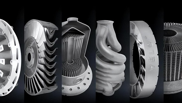
Metal additive manufacturing (AM) has moved from being just a tool for making prototypes to becoming a practical, and often better, way to make products in factories. The discussion is no longer about whether 3d metal printing technology works; it's about how fast, how big, and how well it can perform. We are in a new time period marked by real improvements that are systematically removing the previous barriers to widespread use. This change is not driven by a single breakthrough but by a combination of innovations across three important areas: speed, size, and environmental benefits.
This article goes beyond surface-level excitement to provide a detailed, technical analysis of the forces pushing metal AM into mainstream use. We will explore how multi-laser Powder Bed Fusion (PBF) systems are breaking productivity records, and the complex engineering required to maintain quality at these new speeds. We will look into the rise of real-time process monitoring, including advanced techniques like X-ray imaging, that provide an unprecedented view into the build process, turning a "black box" into a data-rich, controllable system. Furthermore, we will examine how large-format Directed Energy Deposition (DED) is enabling the creation of single-piece metal structures previously thought impossible, and finally, address the critical topic of environmental impact. We will break down the details of powder recycling and conduct a complete life-cycle assessment to provide a data-driven view of metal AM's true environmental impact. This is an expert's look at the technologies making metal 3D printing faster, bigger, and more environmentally friendly than ever before.
Quest for Speed
The most significant bottleneck for mass production in metal AM has historically been the build rate. While single-laser Powder Bed Fusion (PBF) systems are precise, their productivity, often measured in cubic centimeters per hour, has limited their application to smaller, high-value components or one-off parts. The industry's primary answer to this challenge has been the development and improvement of multi-laser PBF systems. Instead of a single laser beam carefully tracing every cross-section, these machines use an array of lasers—typically 4, 8, or even 12—working together on a single, large build plate.
The productivity gains are dramatic. A quad-laser system can, in theory, build parts four times faster than its single-laser counterpart. Some of the latest machines are showing build rates up to 10x higher than systems from just a few years ago, fundamentally changing the cost-per-part equation and opening the door to true series production. However, this leap in speed introduces a significant engineering challenge: the productivity-versus-consistency problem. Simply adding more lasers does not guarantee the production of four or eight identical, high-quality parts. It creates a new set of physics-based problems that must be solved to ensure uniformity across the entire build platform.
The core sources of this inconsistency are thermal variations, stitching defects, and disrupted gas flow. Each laser creates its own thermal history within its designated zone. Without careful management, this can lead to variations in microstructure and residual stress between a part built in the corner and one built in the center. Where the zones of two lasers meet, or "stitch," there is a high risk of defects like lack of fusion porosity or keyhole porosity if the laser parameters and overlap strategy are not perfectly calibrated. Finally, multiple high-power lasers operating simultaneously generate significantly more fumes and spatter, which can overwhelm the inert gas flow system designed to sweep them away. Inadequate gas flow leads to powder bed contamination and part defects.
Overcoming these challenges requires a sophisticated combination of hardware and software. Machine manufacturers invest thousands of hours in developing and validating their systems. This involves careful calibration of each laser's power, focus, and scanner positioning to ensure they are perfectly matched. Advanced software algorithms are used to generate complex laser path strategies that manage thermal input and create seamless, defect-free stitch zones. The validation process is exhaustive, often involving the printing of dozens of test coupons across the entire build plate, which are then subjected to CT scanning, metallographic analysis, and mechanical testing to certify that material properties are uniform, regardless of where the part was built.
| Feature | Single-Laser PBF System | Multi-Laser PBF System |
| Build Rate | Low to moderate (e.g., 5-25 cm³/hr) | High to very high (e.g., 50-150+ cm³/hr) |
| Part Consistency | High; single controlled process environment | A primary challenge; requires extensive calibration |
| Calibration Complexity | Moderate; single laser and optical system | High; requires matching multiple lasers and scanners |
| Cost per Part (at scale) | High, suitable for low volumes | Lower, enables series production economics |
| Ideal Applications | Prototyping, complex medical implants, custom tooling | Aerospace brackets, automotive components, series production |
Quality at Speed
Increasing build speed with multi-laser systems is only half the battle. True industrialization of 3d metal printing technology demands a guarantee of quality for every single part without relying solely on slow and expensive post-build inspection. The solution lies in making the process itself intelligent through real-time, in-place process monitoring. This technology is the critical enabler that supports high-speed production, providing layer-by-layer quality assurance and moving the industry toward the ultimate goal of closed-loop control.
The focal point of this monitoring is the melt pool—the tiny, moving volume of molten metal created by the laser as it fuses the powder. The stability, size, shape, and temperature of the melt pool are direct indicators for the quality of the fusion process. A stable melt pool results in a dense, uniform material structure. An unstable one, prone to fluctuations, can lead to defects like porosity, incomplete fusion, or poor surface finish. It is, in essence, a tiny, moving weld pool that must be perfectly controlled thousands of times per second across millions of vectors in a single build.
To monitor this critical feature, machine builders integrate a suite of sensors that watch the process with superhuman precision. Common sensors include photodiodes, which measure the intensity of the light emitted from the melt pool to infer its temperature, and high-speed cameras, which capture images to analyze its size and shape. Data from these sensors is correlated with known good and bad outcomes to create a "digital signature" for a quality build. Any deviation from this signature during production can be flagged as a potential anomaly.
The most advanced and insightful of these techniques, however, is high-speed X-ray imaging. While other sensors only see the surface of the melt pool, synchrotron-based X-ray imaging allows researchers and engineers to see through the metal and visualize subsurface phenomena in real time. This capability has provided unprecedented insights into defect formation. We can now directly observe the creation of keyhole porosity, a defect that occurs when the laser energy is too concentrated, vaporizing the metal and creating a deep, unstable cavity that can become trapped as a void. We can also visualize how powder particles are ejected from the bed by the laser and the metal vapor plume, a phenomenon known as spatter. These ejected particles can land in unfused areas of the powder bed, creating defects in subsequent layers. These insights, once only discoverable through destructive post-build analysis, are now visible as they happen, enabling a far deeper understanding of the physics of 3d metal printing technology.
The benefits of implementing this level of real-time monitoring are transformative:
- Reduced post-build inspection costs: By identifying potential defects during the build, inspection can be targeted, rather than requiring 100% CT scanning of every part.
- Layer-by-layer quality documentation: Each part is produced with a complete data log of its creation, forming a "digital twin" that serves as an irrefutable quality record.
- Potential for closed-loop control: The future vision is to use this real-time data to make automatic corrections to the laser parameters on the fly, healing a defect before it fully forms.
- Faster process development and qualification: Engineers can "see" the effect of parameter changes instantly, dramatically reducing the time and cost required to develop and certify a process for a new material or geometry.
Pushing Scale
While Powder Bed Fusion dominates the conversation for small to medium-sized intricate parts, a different class of 3d metal printing technology is required to push the boundaries of physical scale. This is the domain of Directed Energy Deposition (DED). Unlike PBF, which builds inside a confined bed of powder, DED systems use a nozzle to deliver powdered or wire-form metal directly into a melt pool created by a laser or electric arc. This process is inherently more scalable, as it is not limited by the size of a build chamber. DED is enabling the production of massive metal structures, with the aerospace industry serving as a primary driver and beneficiary.
DED technology is now producing single-piece aerospace components that exceed 1, 3, or even 5 meters in length. Verifiable examples include large fuselage sections, entire wing ribs, and structural bulkheads for satellites and launch vehicles. These are parts that were traditionally assembled from many smaller, machined components or cut out from enormous blocks of metal. DED offers a fundamentally new approach with unique advantages at this massive scale.
One of the most powerful applications is hybrid manufacturing, where the DED head is integrated into a multi-axis CNC machine. This allows for the additive printing of complex features onto a large, pre-existing substrate like a forging or cast plate. For example, a simple forged shaft can have intricate flanges, bosses, and mounting points printed directly onto it, followed by finish machining in the same setup. This combines the strength of a wrought base material with the design freedom of additive.
DED also offers superior material flexibility. By using multiple powder feeders or switching wire spools, it's possible to change materials during a build. This enables the creation of functionally graded materials—parts that transition from one alloy to another, such as a component with a tough, ductile steel core that transitions to a hard, wear-resistant nickel alloy on the surface. Finally, the deposition rates of DED systems are an order of magnitude higher than PBF, often measured in several kilograms per hour, making the production of large structures economically feasible.
A clear demonstration of DED's value is in the production of large structural ribs for aircraft wings.
- Use Case: Aerospace Structural Rib
- Challenge: A large titanium wing rib is traditionally machined from a billet weighing over 1,000 kg to produce a final part weighing less than 100 kg. This results in a buy-to-fly ratio exceeding 10:1, meaning over 90% of the expensive, energy-intensive material is wasted as machining chips.
- DED Solution: A DED system is used to print a near-net-shape version of the rib, following the general contours of the final part with only a small amount of extra material for final machining.
- Benefits: This approach drastically reduces material waste, often achieving buy-to-fly ratios of 2:1 or 3:1. It also shortens lead times, as the need for massive forgings with long procurement cycles is eliminated. Furthermore, it opens the door to topology optimization, allowing for the creation of lighter, more efficient rib designs that would be impossible to machine conventionally.
The Green Frontier
As 3d metal printing technology matures into a full-scale production method, its environmental impact comes under greater scrutiny. The narrative has often been simplified to "AM reduces waste," but the reality is more complex. True sustainability in metal AM rests on two pillars: mastering the lifecycle of metal powders and taking a holistic, data-driven view of the technology's energy and resource consumption compared to traditional methods.
Taming Powder: Closed-Loop Recycling
In a typical PBF build, the volume of unfused powder can be as much as 95% of the total powder loaded into the machine. Discarding this expensive, energy-intensive material is not an option. Recycling is an economic and environmental necessity. The core technical challenge in powder recycling is contamination control. Reactive metal powders, particularly titanium and aluminum alloys, are highly susceptible to degradation upon exposure to the ambient atmosphere.
From first-hand experience in production environments, the practical difficulties are significant. Every time powder is handled—unpacked from the machine, sieved, and transported—it is exposed to oxygen (O₂) and moisture (H₂O). These contaminants increase the interstitial oxygen content within the powder particles. When this "aged" powder is used in a subsequent build, it can lead to measurable changes in the final part's material properties, such as increased brittleness and reduced fatigue life. For critical applications in aerospace or medical, such variability is unacceptable.
The solution is the implementation of automated, closed-loop powder recycling systems. These systems create a completely inert environment (typically argon or nitrogen gas) for the entire powder lifecycle, from post-build breakout to its reintroduction into the printer.
1. Automated Powder Unpacking: The build chamber is docked with the recycling station, and powder is vacuumed out without exposure to the room's atmosphere.
2. Inert Gas Sieving: The powder is passed through an automated sieve within the inert environment to remove any oversized particles, spatter, or agglomerates that could cause defects.
3. Blending with Virgin Powder: The sieved, recycled powder is automatically blended with a precise, recipe-driven ratio of virgin powder to maintain consistent chemistry and flow characteristics.
4. Automated Transport: The conditioned powder is then transported, typically via pneumatic conveying, directly back to the printer's dispenser, ready for the next build.
The Full Picture: A Life-Cycle View
To accurately assess the sustainability of metal AM, we must look beyond a single metric and employ a Life-Cycle Assessment (LCA) framework. This compares the entire environmental impact of creating a part with AM versus a traditional subtractive benchmark, like CNC machining, from raw material extraction to the part's end of life.
A common point of debate is the energy consumption of the printing process itself. A high-power laser system is indeed energy-intensive, and the kWh/kg to print a part can be higher than the kWh/kg to machine it. However, this comparison is misleadingly narrow. The true environmental cost of the subtractive route lies in the massive amount of material that is produced, processed, shipped, and then machined away as waste. The energy required to mine bauxite, refine it into aluminum, and form it into a huge billet often dwarfs the energy used in the final manufacturing step.
Metal AM's sustainability proposition becomes clear when viewed through this holistic lens. The radical reduction in material waste is the single most significant factor. By printing parts to near-net shape, AM minimizes the "buy-to-fly" ratio, saving not only material but all the embodied energy and carbon footprint associated with producing that material in the first place.
| LCA Factor | Traditional CNC Machining | Advanced Metal AM |
| Raw Material Production | Very high; requires large billets to accommodate tool access and work holding. | Low; only the material for the part plus minimal supports is needed. |
| Energy Consumption (per part) | Moderate for machining, but extremely high total energy embodied in wasted material. | Process can be energy-intensive, but overall energy is lower due to material savings. |
| Material Waste (Buy-to-Fly) | High to very high (e.g., 5:1 to 20:1 for aerospace components). | Very low (e.g., 1.1:1 to 3:1). |
| Supply Chain Impact | Complex and lengthy; relies on centralized foundries, forges, and machine shops. | Enables decentralized, on-demand production, reducing transport emissions and inventory. |
| Use-Phase Efficiency | Design limited by manufacturing constraints; lightweighting is difficult. | Enables topology optimization for radically lighter parts, saving fuel/energy over the product's lifetime. |
When the entire lifecycle is considered, the conclusion is clear. The dramatic savings in material waste and the profound performance gains from lightweighting during the part's use-phase often make 3d metal printing technology the far more sustainable choice for manufacturing complex components.
The Industrialization is Here
The advancements in speed, scale, and sustainability are not isolated improvements. They are an interconnected ecosystem of technologies that are collectively pushing 3d metal printing technology over the threshold into true industrial production. High-speed, multi-laser systems are making the cost-per-part economics viable for series production, but they rely entirely on the quality assurance provided by real-time process monitoring. Simultaneously, large-format DED is unlocking new applications for massive structures, while sophisticated, closed-loop sustainability practices are making the entire process more efficient and environmentally responsible.
This convergence marks a definitive shift. We are moving from a world where metal AM was an exotic tool for complex problems to one where it is a foundational pillar of modern manufacturing. This technology is no longer just changing the shape of parts; it is reshaping the architecture of supply chains, the timeline of product development, and the very future of how we make things. The industrialization of metal 3D printing is not a future promise; it is happening now.
