In the world of precision manufacturing, turning parts are fundamental components found in countless machines and devices. From the humble screw to complex engine shafts, CNC turning is a cornerstone process for creating cylindrical geometries. This article delves deep into the world of turned components. We will explore what they are, how they differ from other machined parts, suitable materials, achievable precision, and the entire journey from tool setup to final quality inspection. Whether you're an engineer designing a new product or a procurement specialist sourcing components, this guide provides the substantive, experience-driven knowledge you need to make informed decisions about precision turned parts.
What Are Turning Parts?
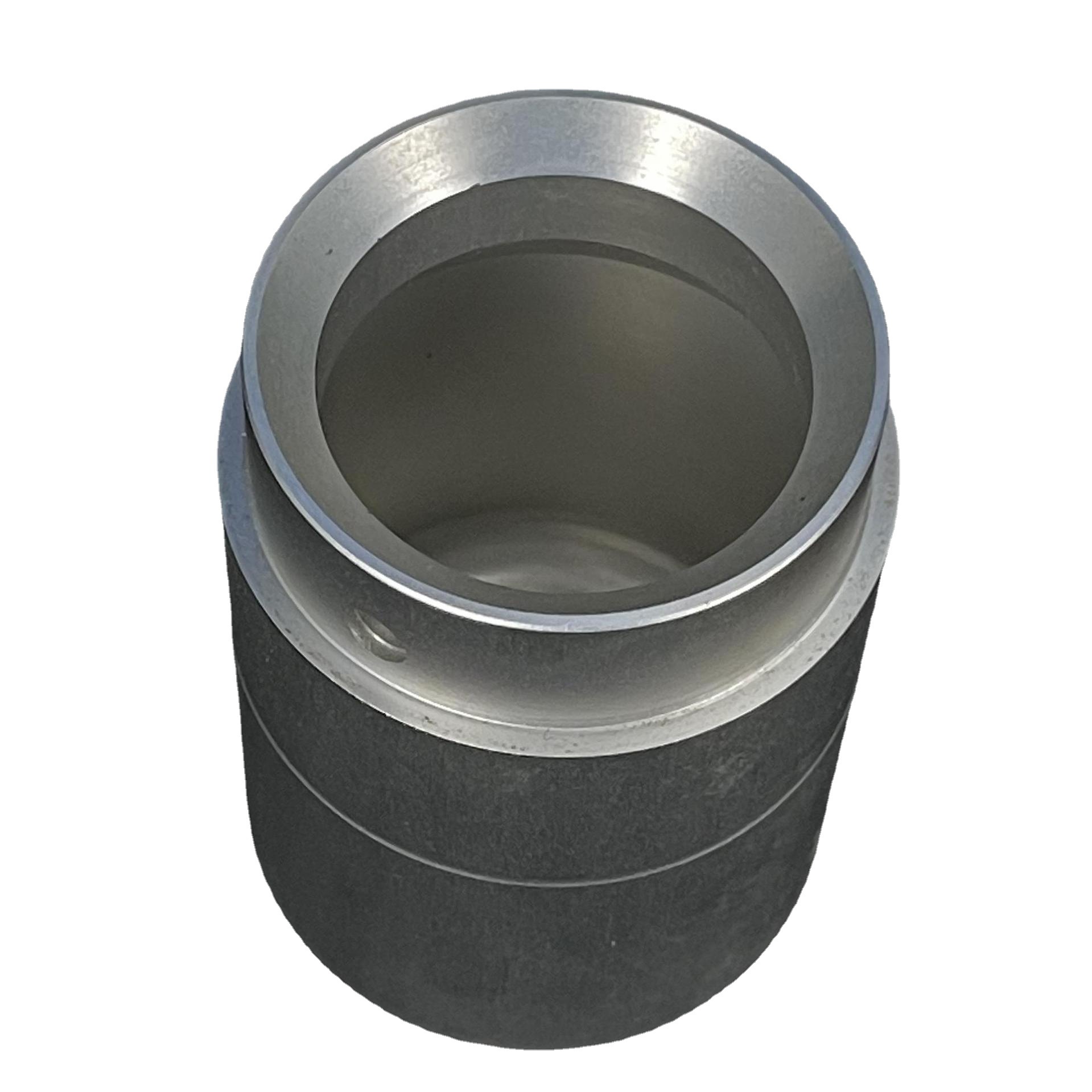
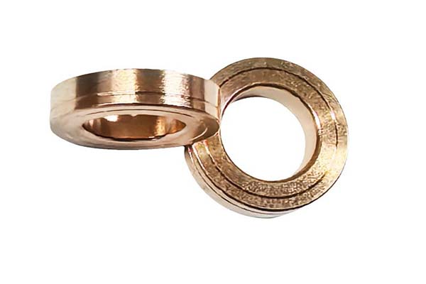
Turning parts, or turned components, are workpieces shaped by a subtractive manufacturing process called turning. In this operation, the workpiece rotates at high speed while a stationary cutting tool removes material. The primary goal is to produce parts with cylindrical symmetry, such as shafts, pins, bushings, and connectors. The turning process excels at creating features like external diameters (ODs), internal diameters (IDs/bores), grooves, tapers, and threads. A classic real-world example is a precision shaft for an electric motor. Starting as a simple metal bar, the turning center machines various stepped diameters, bearing seats, and a keyway, transforming raw material into a critical, rotationally balanced component.
How Do They Differ From Milled Parts?
Understanding the distinction between turned and milled parts is crucial for selecting the right manufacturing process. The core difference lies in the movement of the workpiece and the cutting tool.
- Turning: The workpiece rotates, and the cutting tool moves in linear axes. It's ideal for radially symmetric parts.
- Milling: The cutting tool rotates, and the workpiece is stationary or moves in linear axes. It's used for complex 3D contours, pockets, and flat surfaces.
Consider a simple gear. A spur gear blank (a plain disc) is a perfect job for turning. However, cutting the actual gear teeth into the blank's circumference requires a milling or dedicated gear hobbing process. The table below summarizes key differences:
| Feature | Turning Parts | Milled Parts |
|---|---|---|
| Primary Geometry | Cylindrical, rotational symmetry | Prismatic, complex 3D shapes |
| Workpiece Motion | Rotates | Stationary or linearly fed |
| Tool Motion | Linear (X, Z axes) | Rotational & Linear (X, Y, Z axes) |
| Typical Features | ODs, IDs, grooves, threads, tapers | Pockets, slots, complex profiles, flat faces |
| Surface Finish | Often excellent due to continuous cut | Can show toolpath marks on flat areas |
Which Materials Suit Turning Best?
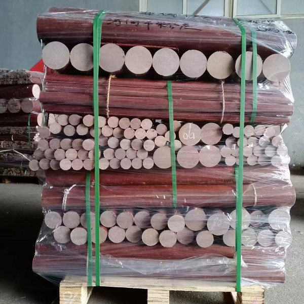
The turning process is remarkably versatile with materials. The choice depends on the part's function, required strength, corrosion resistance, and cost.
- Metals: This is the most common category.
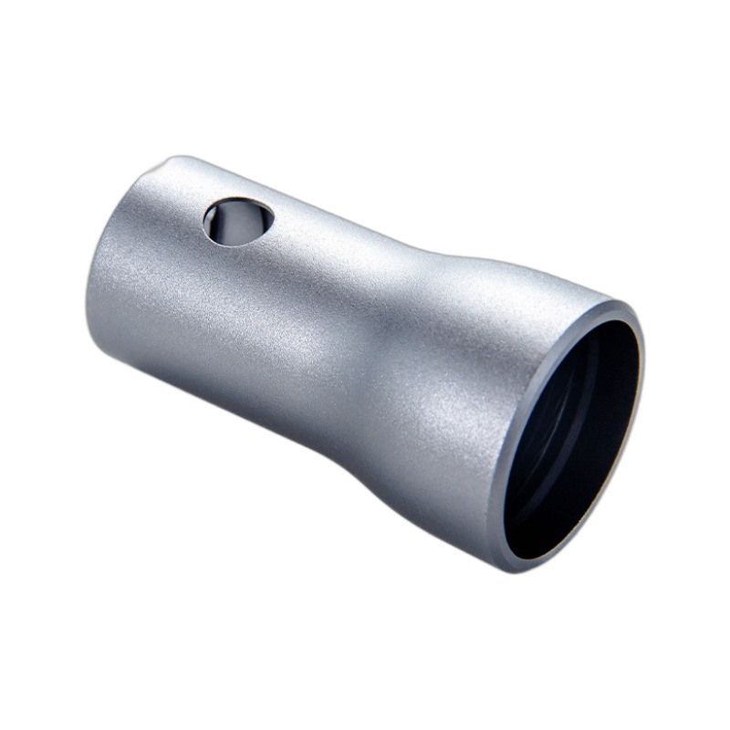
- Aluminum Alloys (e.g., 6061, 7075): Excellent for high-speed turning, offering a great strength-to-weight ratio and good machinability. Widely used in aerospace and automotive turning components.
- Stainless Steels (e.g., 303, 304, 316): Chosen for their corrosion resistance and strength. 303 is specifically formulated for superior machinability.
- Carbon & Alloy Steels (e.g., 1045, 4140): Provide high strength and wear resistance for shafts and pins.
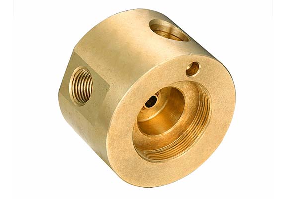
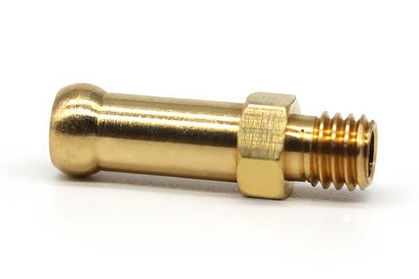
- Brass & Copper Alloys: Offer excellent conductivity, corrosion resistance, and a smooth finish, perfect for plumbing and electrical turned parts.
- Plastics: Engineering plastics like Delrin (POM), Nylon (PA), and PTFE (Teflon) are easily turned to create lightweight, corrosion-resistant, and low-friction insulators, bushings, and seals.
- Expert Insight: While most materials can be turned, "machinability" is key. A material like free-machining brass produces small, broken chips and allows very high speeds, while a gummy material like pure aluminum or some stainless steels requires specific tool geometries and cutting parameters to manage chip control and achieve a good surface finish.
What Tolerances Can Turning Hold?
Modern CNC turning centers are capable of holding very tight dimensional tolerances. For standard production precision turned parts, a tolerance of ±0.025 mm (±0.001") is routinely achievable. With optimized processes, careful tooling, and temperature control, tolerances can be pushed to ±0.0127 mm (±0.0005") or even tighter for critical features.
It's important to balance precision with cost. Specifying an unnecessarily tight tolerance on all dimensions can exponentially increase production time and cost due to the need for slower speeds, specialized tooling, and extensive inspection. A best practice is to apply geometric dimensioning and tolerancing (GD&T) principles, calling out tight tolerances only where they are functionally critical for fit or performance.
Why Choose CNC Turning Over Manual?
The shift from manual to CNC (Computer Numerical Control) turning represents a monumental leap in manufacturing capability.
- Repeatability & Consistency: Once the program is verified, a CNC lathe will produce the first and the thousandth turning part identically. Manual turning relies heavily on operator skill for each part.
- Complexity & Speed: CNC machines can produce complex geometries (e.g., compound curves, intricate profiles) that are impractical or impossible manually. They also operate at higher, more consistent speeds.
- Reduced Human Error & Integration: The process is automated, minimizing scrap. CNC lathes can be integrated with robotics for lights-out manufacturing, running unattended for extended periods.
- Case in Point: Imagine an order for 10,000 custom drive shafts with multiple diameters, grooves, and a special thread. A manual machinist would take immense time per part with high variability. A CNC lathe, after a one-time program and tooling setup, can run the entire batch with minimal intervention, ensuring every shaft meets the exact digital blueprint.
How Are Tools Set Up for a Turning Job?
Proper tool setup is the foundation of a successful turning operation. It's a blend of science and hands-on experience.
- Tool Selection: Based on the material and features, the engineer selects appropriate insert grades (carbide, CBN, diamond), geometries (for roughing, finishing, threading), and tool holders.
- Machine Setup: The raw material (bar stock) is securely clamped in the chuck or collet. Tool holders are mounted into the machine's turret in a predefined order.
- Tool Offsetting: This is a critical step. Using a tool presetter or the machine's probe, the precise position (X and Z coordinates) of each tool's cutting tip is measured and entered into the CNC control. This tells the machine exactly where the tool is in relation to the workpiece.
- Program Zero: A reference point on the workpiece (often the finished face or centerline) is set as the program's origin (zero point).
- Dry Run: The program is often run without cutting (or with a safe distance from the part) to verify tool paths and avoid collisions.
What Surface Finishes Are Possible?
Surface finish on turned parts, measured in micro-inches (µin) or microns (µm Ra), is vital for function, wear, and aesthetics. CNC turning can achieve a wide range:
- Rough Turned: 125-250 µin Ra (3.2-6.3 µm). Typical for non-critical surfaces.
- Standard Finished: 32-125 µin Ra (0.8-3.2 µm). Common for most functional components.
- Fine Finished: 16-32 µin Ra (0.4-0.8 µm). Achieved with sharp tools, high speeds, low feeds, and proper cutting fluids. Required for sealing surfaces or bearing seats.
- Very Fine/Polished: < 8 µin Ra (< 0.2 µm). May require secondary operations like polishing or grinding after turning.
Factors influencing finish include feed rate (lower feed = finer finish), cutting speed, tool nose radius, insert sharpness, and machine rigidity.
How Is Part Quality Inspected?
Ensuring turning parts meet specifications requires a rigorous, multi-stage inspection protocol that blends tools with expertise.
- First-Article Inspection (FAI): A comprehensive check of the first part off the machine using high-precision equipment like Coordinate Measuring Machines (CMM) to verify all dimensions against the CAD model.
- In-Process Inspection: Periodic checks of critical dimensions during the production run using calibrated instruments:
- Micrometers & Calipers: For diameter and length.
- Dial Indicators: For checking runout and concentricity.
- Thread Gauges (Go/No-Go): For verifying thread accuracy.
- Surface Roughness Testers: For measuring Ra values.
- Final Audit: A statistical sample from the completed batch is inspected to ensure consistent quality before shipment. Documentation, including inspection reports and material certifications, is provided for traceability and proof of compliance.
Conclusion
Turning parts are the unsung heroes of the mechanical world, enabled by the sophisticated yet reliable turning process. From material selection and tolerance planning to the execution on advanced CNC turning centers and final quality verification, each step requires deep technical knowledge and practical experience. By understanding these principles, designers and buyers can effectively collaborate with manufacturers to produce precision turned components that are not only geometrically accurate but also optimal in performance, cost, and reliability.
FAQ
What are the most common applications for turning parts?
They are ubiquitous in industries like automotive (axles, valves), aerospace (landing gear components, fasteners), medical (implants, surgical tool handles), and fluid power (hydraulic fittings, valve bodies).
Can turning create complex, non-cylindrical shapes?
Yes, with modern CNC turning centers equipped with live tooling (rotating tools) and Y-axis capabilities, operations like milling, drilling, and slotting can be performed on the turned part in one setup. This is known as turn-mill or mill-turn machining.
How does material hardness affect the turning process?
Harder materials (like tool steels) require harder, more wear-resistant cutting tools (e.g., CBN inserts), lower cutting speeds, and more rigid machine setups. They generate more heat and pose greater challenges for tool life and surface finish.
What is the main advantage of Swiss-type turning?
Swiss-type lathes are specialized for producing long, slender, and complex turning parts with extreme precision. The guide bushing provides exceptional support close to the cutting tool, minimizing deflection and allowing for intricate features on small-diameter components.
Contact Yigu for Custom Manufacturing
At Yigu Technology, we understand that precision turning parts are more than just specifications on a drawing; they are critical to the performance and success of your final product. Leveraging our expertise in advanced CNC turning and multi-axis mill-turn systems, we provide not just machining, but manufacturing solutions. Our engineering team partners with you from the design stage, offering actionable insights on design for manufacturability (DFM) to optimize for cost, lead time, and performance. We combine rigorous inspection protocols with transparent communication, ensuring the turned components you receive meet the highest standards of quality and reliability. Let us be your trusted partner in turning your designs into reality.