In the world of manufacturing, creating precise cylindrical parts is a fundamental need. From the humble automotive shaft to complex aerospace components, one process stands as a cornerstone: machining turning. It's one of the most common and essential subtractive manufacturing techniques, but what exactly does it entail, and how can it be optimized for quality and efficiency? This comprehensive guide dives deep into the art and science of turning. We'll explore its core principles, the machinery involved, material considerations, tooling strategies, and the critical parameters that separate a good part from a great one. Whether you're an engineering student, a workshop manager, or a procurement specialist, understanding the nuances of turning operations will equip you with the knowledge to make informed decisions and appreciate the precision behind countless everyday objects.
What Is Turning in Machining?
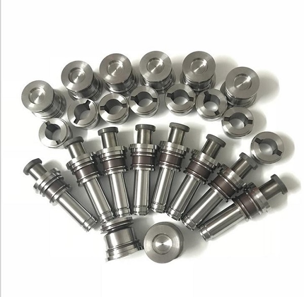
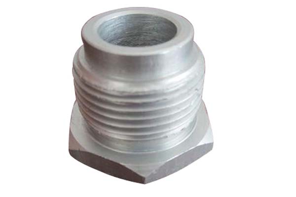
Turning is a machining process where a cutting tool, typically a non-rotary tool bit, removes material from a rotating workpiece. The primary goal is to generate cylindrical surfaces, though it can also produce tapers, contours, and facing operations. The workpiece is held and rotated by a spindle, while the tool is fed linearly along its axis of rotation or across its end. This is distinct from milling, where the tool rotates and the workpiece is generally stationary. The heart of any turning setup is the lathe machine. Turning operations are revered for their ability to achieve exceptional surface finish, tight dimensional tolerances, and high concentricity. Common features created include external diameters (OD turning), internal diameters (boring), facing (creating flat surfaces on the end), grooving, and threading. Its applications are virtually limitless, spanning industries like automotive, medical device manufacturing, energy, and general machinery.
How Does a Lathe Work in Turning Operations?
Understanding the lathe's components is key to grasping the turning process. A modern CNC lathe's main parts include:
- Headstock: Houses the main spindle, which grips the workpiece via a chuck or collet. It controls the rotational speed (RPM).
- Tailstock: Supports the free end of longer workpieces with a center, providing stability.
- Tool Turret: Holds multiple turning tools and indexes them into position automatically under CNC command.
- Carriage & Cross-Slide: Move the tool turret in the Z-axis (along the bed, parallel to the spindle) and X-axis (perpendicular to the bed), enabling complex movements.
- CNC Control Unit: The "brain" that interprets G-code and drives the motors for precise axis movement and spindle control.
A basic operation sequence is: The workpiece is securely clamped. The spindle rotates it at a predetermined speed. A selected cutting tool is brought into contact with the workpiece. The tool then moves along a programmed path, shearing away material in the form of chips to create the desired shape. The synchronized control of rotation and linear tool movement is what defines the process.
What Materials Are Best Suited for Turning?
While turning can handle a vast array of materials, machinability—a combination of factors like tool wear, power consumption, and achievable finish—varies greatly. Here’s a breakdown:
| Material Category | Common Examples | Machinability & Key Considerations |
|---|---|---|
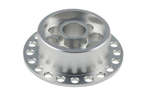
| Metals | Aluminum Alloys, Brass, Mild Steel | Excellent to good machinability. Often produce discontinuous chips. May require specific tool geometries. |
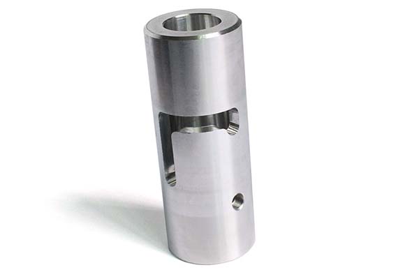
| Engineering Alloys | Stainless Steel (e.g., 304, 316), Titanium, Inconel | More challenging. They are harder, work-harden, and generate high heat. Require robust setups, specialized tooling (e.g., coated carbide), and often coolant. |
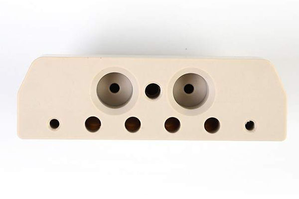
| Plastics & Composites | Delrin (POM), Nylon, PTFE, Peek | Generally easy to machine but require sharp tools, higher speeds, and lower feeds to avoid melting or deforming. Dust extraction is often needed for composites. |
From an expertise perspective, successfully turning a tough alloy like Inconel 718 requires a specific approach: using a rigid machine, micro-grain carbide tools with a positive rake geometry, a conservative cutting speed to manage heat, and high-pressure coolant directed precisely at the cutting edge to break chips and reduce thermal load.
What Are the Main Types of Turning Tools?
Selecting the right tool is critical. Tools are primarily defined by their insert geometry, material, and holder.
- By Insert Shape & Function:
- Roughing Tools (80° Diamond): Strong geometry for heavy material removal.
- Finishing Tools (55° or 35° Diamond): Sharp for fine cuts and superior surface finish.
- Grooving & Parting Tools: Narrow inserts for cutting grooves or severing a part.
- Threading Tools: Ground to the precise thread profile (e.g., 60° for metric threads).
- Boring Bars: For internal diameter machining, requiring high rigidity to avoid deflection.
- By Cutting Material:
- Carbide (Most Common): The workhorse. Offers a great balance of hardness and toughness. Coatings like TiAlN (for heat resistance) or AlTiN (for abrasion resistance) dramatically enhance performance.
- High-Speed Steel (HSS): Tougher but less wear-resistant than carbide. Good for intermittent cuts or intricate form tools.
- Ceramic & CBN (Cubic Boron Nitride): For high-speed machining of hard ferrous materials (e.g., hardened steel).
- Diamond (PCD): For highly abrasive non-ferrous materials like silicon aluminum or carbon fiber composites.
A professional tip is to never underestimate tool holder quality. A precision-ground VDI or BTS holder ensures minimal runout, which is directly linked to tool life and part accuracy.
How Do Cutting Speed and Feed Rate Affect Surface Finish?
Cutting speed (Vc) and feed rate (fn) are the two most influential parameters in determining productivity, tool wear, and surface finish. They form the core of machining calculations.
- Cutting Speed (Vc): The speed at which the workpiece surface moves past the cutting tool (measured in m/min or SFM). Too high a speed generates excessive heat, accelerating tool wear. Too low a speed leads to built-up edge and poor finish.
- Feed Rate (fn): The distance the tool advances along the workpiece per revolution (measured in mm/rev or IPR). It directly controls chip thickness.
The relationship to surface finish is governed by a simple formula: Theoretical Surface Roughness (Ra) ≈ (Feed Rate²) / (8 × Nose Radius). This shows that to achieve a smoother finish, you should:
- Reduce the feed rate.
- Use a tool with a larger nose radius.
- Ensure stability to avoid vibrations that worsen actual roughness.
For example, finishing a 100mm diameter carbon steel shaft might use a cutting speed of 250 m/min and a feed rate of 0.1 mm/rev with a 0.8 mm nose radius tool. Roughing the same part might use the same speed but a feed of 0.3 mm/rev to maximize metal removal.
What Role Does Coolant Play in Turning?
Coolant, or metalworking fluid, is far more than just a cooling agent. Its multi-faceted roles are essential in modern turning operations:
- Heat Dissipation: Carries heat away from the cutting zone, protecting both the tool and the workpiece from thermal deformation.
- Lubrication: Reduces friction between the tool's flank face and the workpiece, lowering power consumption and improving surface finish.
- Chip Evacuation: Washes away chips from the cutting zone, preventing recutting and potential damage to the workpiece surface.
- Corrosion Protection: Protects the machine tool and freshly machined part from rust.
The choice between flood coolant, high-pressure through-tool coolant (up to 70 bar or more), or Minimum Quantity Lubrication (MQL) is strategic. High-pressure through-tool coolant is particularly effective in deep hole boring or when machining sticky materials like aluminum, as it breaks long chips into manageable "C" shapes, enhancing safety and process reliability.
How Can Tool Wear Be Minimized During Turning?
Tool wear is inevitable, but its rate can be managed. The primary wear mechanisms are abrasion, adhesion (built-up edge), and diffusion. Here’s a minimization strategy:
- Optimize Cutting Parameters: Follow tool manufacturer recommendations for speed and feed. Avoid speeds in the "danger zone" that cause excessive heat.
- Select the Right Tool Geometry & Coating: A sharper positive rake geometry reduces cutting forces. Modern PVD coatings like AlTiN provide a hard, thermally insulating barrier.
- Maximize Rigidity: The mantra is "short and stout." Use the shortest possible tool holder and overhang. Ensure the workpiece is well-supported. Rigidity dampens vibration, the enemy of tool life.
- Implement Effective Coolant Strategy: As discussed, proper cooling and lubrication directly combat thermal wear.
- Monitor and Adapt: Listen to the cut. Observe chip color (blue chips often mean too much heat) and shape. Implement tool wear monitoring systems on CNC machines that can adjust offsets or signal for a change.
From an experience standpoint, I once resolved a chronic tool wear issue in a production run of stainless steel fittings not by changing the tool, but by simply increasing the tool nose radius and implementing a more consistent, high-pressure coolant flow. Tool life increased by over 300%, showcasing that system optimization is as critical as tool selection.
How Does CNC Turning Differ from Manual Turning?
This contrast highlights the evolution of the turning process.
| Aspect | Manual Turning | CNC (Computer Numerical Control) Turning |
|---|---|---|
| Operation & Skill | Fully controlled by a skilled machinist using handwheels. Relies on artisan's experience and feel. | Programmed via G-code. The operator sets up, loads program, and monitors. Less dependent on real-time manual dexterity. |
| Precision & Repeatability | High skill-dependent precision. Repeatability for multiple parts is challenging and slower. | Extremely high and consistent precision. Perfect for mass production and complex geometries. |
| Complexity of Parts | Suitable for simple geometries, one-offs, and repairs. | Capable of producing highly complex parts with contours, tapers, and multiple features in a single setup. |
| Setup & Changeover | Relatively quick for simple jobs. | Longer initial setup and programming time. Changeover is fast once programs are proven. |
| Core Advantage | Flexibility for prototypes and quick jobs. Lower initial machine cost. | Unmatched productivity, consistency, and capability for complex, high-volume work. |
The industry trend is firmly toward CNC turning, especially with the advent of multi-axis turning centers and mill-turn machines that can complete a part in a single chucking, dramatically improving accuracy and reducing lead time.
Conclusion
Machining turning is a dynamic and foundational pillar of manufacturing. From understanding the basic interaction between a rotating workpiece and a cutting tool to mastering the complex interplay of parameters like speed, feed, and tool geometry, effective turning requires both science and practical expertise. The shift from manual to CNC turning has expanded the possibilities for complexity and scale, but the core principles remain. By selecting the right materials, implementing strategic tooling and coolant practices, and vigilantly managing tool wear, manufacturers can achieve the holy grail: efficient production of high-precision, high-quality components. As materials evolve and demands for precision grow, the art of turning will continue to adapt, driven by innovation in tooling, machine technology, and the accumulated knowledge of skilled engineers and machinists.
FAQ on Machining Turning
- What is the basic difference between turning and milling?
In turning, the workpiece rotates and the cutting tool moves in a linear fashion. In milling, the cutting tool rotates and the workpiece is stationary or moves linearly. Turning is ideal for cylindrical parts, while milling is used for flat or complex contoured surfaces. - Can turning create internal features?
Absolutely. Processes like boring (enlarging a pre-drilled hole), internal grooving, and threading are standard internal turning operations performed using boring bars and specialized internal tools. - What does "chatter" mean in turning and how do I fix it?
Chatter is a violent vibration that leaves poor surface finish and damages tools. It's caused by lack of rigidity. Fixes include shortening tool overhang, using a more robust tool holder, adjusting speed and feed, employing anti-vibration boring bars, or ensuring proper workpiece support. - How do I choose between carbide and HSS tools?
Choose carbide for most applications, especially on CNC lathes, for its wear resistance and ability to handle higher speeds. HSS is preferable for low-speed applications, intricate form tools, or on older manual machines where its toughness is an advantage. - What is a "live tooling" on a CNC lathe?
Live tooling refers to driven tools mounted on the turret of a CNC lathe. They can rotate and perform milling, drilling, and tapping operations while the workpiece remains stationary. This enables complex parts to be completed in one setup on a mill-turn center.
Contact Yigu for Custom Manufacturing
At Yigu Technology, we view machining turning not just as a process, but as a critical enabler of innovation and reliability. We understand that the journey from a raw material to a flawless precision component hinges on deep technical expertise, state-of-the-art CNC turning infrastructure, and an unwavering commitment to quality control.
Our perspective is that true value in custom manufacturing is delivered through engineering partnership. Our team of seasoned engineers doesn't just execute drawings; we analyze them for manufacturability. We proactively advise on optimal material selection, ideal tolerances for function and cost, and the most efficient turning operations sequence. By leveraging our advanced multi-axis turning centers and rigorous process monitoring, we ensure that every part, whether a prototype or a production run of thousands, meets the highest standards of dimensional accuracy, surface finish, and consistency.
If you are looking for a partner that combines technical depth in turning processes with a collaborative approach to solve your most challenging custom manufacturing needs, contact Yigu Technology. Let's transform your designs into reality.