The selection and optimization of CNC machined products require a strategic understanding of the interplay between material properties, machine capabilities, design geometry, and post-processing to achieve the ideal balance of functionality, quality, and cost.
In the world of modern manufacturing, CNC machined products are fundamental building blocks. From a simple aluminum bracket to a complex titanium aerospace component, these parts are defined by their precision, repeatability, and versatility. However, achieving the optimal result—a part that performs flawlessly, is delivered on time, and fits the budget—requires moving beyond simply sending a CAD file to a machine shop. It demands an informed collaboration between designer and manufacturer. This guide provides a comprehensive, practical framework for navigating the entire lifecycle of a CNC machined part. We'll demystify the technical aspects of different axis configurations, explain how to specify realistic tolerances, break down the cost drivers, and reveal how strategic post-processing can unlock enhanced performance. Whether you're an engineer, a product designer, or a procurement specialist, this knowledge will empower you to make smarter decisions and effectively partner with your machining supplier.
Introduction
The term CNC machined products encompasses a vast array of components, but they all share a common genesis: a digital design is translated, via computer-aided manufacturing (CAM) software, into precise tool movements that sculpt a solid block of material. This subtractive process offers unparalleled flexibility but comes with its own set of rules and trade-offs. The choice between a 3-axis and a 5-axis machine isn't arbitrary—it fundamentally changes what geometries are possible and economical. Specifying a surface finish of 32 µin Ra versus 8 µin Ra isn't just about looks; it affects friction, wear, and sealing capability. This article is designed to be your practical companion through these decisions. We'll start with the basics of what CNC machining is, then delve into the critical choices of material and machine, and finally explore the finishing touches and cost considerations that define a successful project. By the end, you'll have a clear roadmap for developing and sourcing CNC machined parts that excel in both form and function.
What exactly are CNC machined products?
CNC machined products are components manufactured through a subtractive process controlled by a computer numerical control (CNC) system. A computer program (G-code) directs the movement of cutting tools on multiple axes to selectively remove material from a solid workpiece (a "blank" or "billet") until the final shape is achieved.
The core value proposition of CNC machining lies in its:
- Precision and Repeatability: Once a program is verified, it can produce thousands of identical parts with microscopic accuracy.
- Material Versatility: It can process metals (aluminum, steel, titanium), plastics (PEEK, Delrin), composites, and even woods.
- Complex Geometry: Capable of creating intricate features like deep pockets, complex curves, and precise internal channels that are difficult or impossible with casting or forging.
- Rapid Prototyping to Production: The same digital file and similar processes can be used for a one-off prototype and a production run of 10,000, ensuring consistency from validation to final product.
A simple yet ubiquitous example is a laptop's aluminum unibody chassis. It starts as a solid block of aluminum. A CNC machine mills out the interior pockets for the battery and motherboard, drills all mounting holes, cuts the precise edges, and even machines the speaker grilles—all in a series of automated, highly repeatable steps.
Which materials work best for CNC machining?
While CNC machines can cut a wide range of materials, some are inherently better suited due to their machinability—a combination of how easily they are cut, the surface finish they yield, and their impact on tool life.
| Material Category | Example Alloys/Polymers | Machinability Rating & Notes | Best For Applications Needing… |
|---|---|---|---|
| Aluminum Alloys | 6061-T6, 7075-T6 | Excellent. Cuts cleanly, allows for high speeds, good surface finish. The "default" choice for many projects. | Lightweight structural parts, enclosures, heat sinks, prototypes. |
| Free-Machining Steels | 12L14, 1215 | Excellent. Contains additives like sulfur or lead that break chips easily, enabling fast production. | High-volume production of shafts, pins, and fittings where strength requirements are moderate. |
| Stainless Steels | 303, 304, 316 | Fair to Good. 303 is designed for machining; 304/316 are tougher and can work-harden, requiring careful tool selection. | Corrosion-resistant parts for medical, marine, or food processing applications. |
| Plastics (Engineering) | Acetal (Delrin®), Nylon (PA 6/66), PEEK | Good to Fair. Require sharp tools, specific speeds/feeds, and often coolant to manage heat (which can melt plastic). | Electrical insulators, low-friction bearings, chemical-resistant components. |
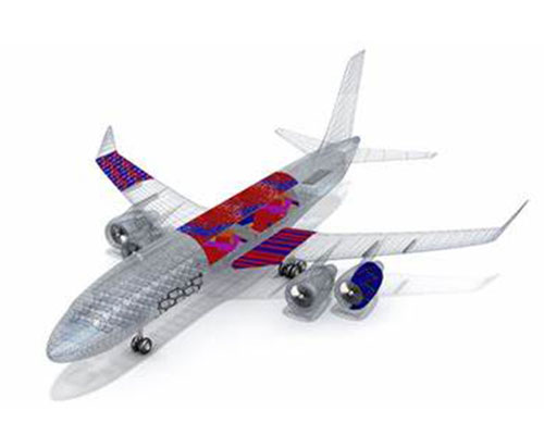
| Titanium Alloys | Ti-6Al-4V (Grade 5) | Difficult. Low thermal conductivity causes heat to concentrate at the cutting edge, requiring slow speeds, high-pressure coolant, and rigid setups. | High strength-to-weight aerospace and medical implant components. |
Material Selection Case Study: A robotics company designed a complex gear for a robotic arm joint. The initial prototype was machined from stainless steel 304 for its strength. However, during testing, the gear produced excessive noise and wore quickly. After a material consultation with their machinist, they switched to Cast Nylon 6. While less strong in absolute terms, the nylon's self-lubricating properties eliminated noise, reduced wear by 70%, and cut machining time by 40% due to nylon's superior machinability, leading to a better-performing, lower-cost final product.
How do 3-, 4-, and 5-axis machines differ in capability?
The number of axes a CNC machine can move simultaneously directly dictates the complexity of parts it can produce in a single setup.
| Axis Configuration | Movement Capability | Key Advantages | Limitations & Best Use Cases |
|---|---|---|---|
| 3-Axis CNC | Tool moves in linear X, Y, and Z directions. | Most common and cost-effective. Simple programming and operation. Excellent for prismatic parts (parts with all features on top or perpendicular sides). | Cannot machine complex contours or undercuts without re-fixturing. Best for: 2.5D parts, plates, brackets, and simple molds. |
| 4-Axis CNC | Adds a rotary axis (usually the A-axis), allowing the workpiece to rotate. | Can machine features around the circumference of a part in one setup (e.g., drilling holes on the side of a cylinder, machining cam lobes). | Still limited for free-form 3D shapes. Best for: Cylindrical parts, indexing operations, and parts requiring features on multiple sides. |
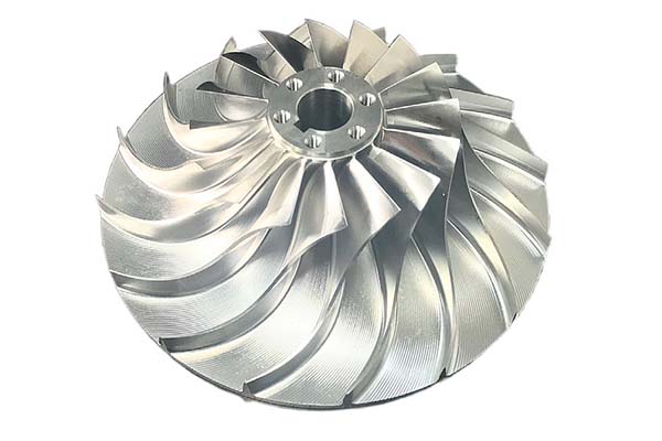
| 5-Axis CNC | Adds a second rotary axis (B or C-axis) to the three linear axes. Tool can approach the workpiece from any direction. | Single-setup machining of incredibly complex geometries (turbine blades, impellers). Improved surface finish from optimal tool angle. Ability to machine undercuts. | Higher machine cost, more complex programming, and requires advanced operator skill. Best for: Complex aerospace, medical, and automotive components. |
Visualizing the Difference: Imagine machining a simple cube with a pocket on each of its six faces. On a 3-axis machine, you would need to manually re-fixture the cube six times, introducing potential alignment errors each time. On a 5-axis machine, the cube could be held once, and the spindle would tilt and rotate to access all sides automatically, ensuring perfect alignment and much faster production.
Key tolerances and surface finishes achievable
Understanding standard capabilities helps set realistic expectations and avoids over-specifying, which drives up cost.
Standard Tolerances
- Milled Parts: A standard tolerance of ±0.005" (0.13 mm) is readily achievable. With care, ±0.001" (0.025 mm) is common for precision work.
- Turned Parts: Lathes can often hold slightly tighter tolerances, with ±0.0005" (0.0127 mm) possible on diameters.
Crucial Note: Tolerances follow an exponential cost curve. Specifying a ±0.0005" tolerance when ±0.005" would function can easily increase the part cost by 300-500% due to slower machining, specialized inspection, and higher scrap rates.
Standard Surface Finishes
Surface finish is measured in micro-inches (µin) or micrometers (µm) Ra (average roughness).
- As-Machined: 63-125 µin Ra. Visible tool marks.
- Standard Machined: 32-63 µin Ra. Good for many functional applications.
- Fine Machined: 16-32 µin Ra. Requires optimized toolpaths and tools; suitable for bearing surfaces.
- Ground/Lapped: < 16 µin Ra. Achieved through secondary processes like grinding or polishing; essential for sealing surfaces or optics.
Programming essentials: CAD to G-code workflow
The journey from your idea to a machined part follows a defined digital pipeline:
- CAD (Computer-Aided Design): You (the designer) create a 3D model of the part using software like SolidWorks, Fusion 360, or CATIA. This model defines the final geometry.
- CAM (Computer-Aided Manufacturing): A machinist or programmer uses CAM software (e.g., Mastercam, Fusion 360 CAM) to "toolpath" the CAD model. They select tools, define cutting strategies (e.g., roughing, finishing), set speeds/feeds, and simulate the entire process to avoid collisions.
- Post-Processing: The CAM software generates a generic toolpath, which a post-processor translates into G-code specific to the brand and model of the target CNC machine (e.g., a Haas VF-2 vs. a Mazak Integrex).
- Machine Setup & Run: The machinist loads the G-code, sets up the material and tools on the machine, and runs the program, often starting with a dry run or a single-step verification.
How can post-processing enhance part performance?
The work of the CNC machine is often just the first step. Post-processing operations add critical functional properties.
- Heat Treatment (e.g., Annealing, Tempering, Hardening): Alters the material's microstructure to increase hardness, strength, or relieve internal stresses induced during machining.
- Plating & Coating: Anodizing (for aluminum) adds corrosion and wear resistance. Electroless Nickel Plating provides a hard, uniform, corrosion-resistant layer. Powder Coating offers durable color and protection.
- Precision Grinding/Honing: Used to achieve tolerances and surface finishes beyond the capability of standard milling or turning, such as for hydraulic valve spools or fuel injector nozzles.
- Vibratory/Tumble Finishing: A batch process that removes burrs (sharp edges) and imparts a uniform, smooth edge radius, improving safety and part handling.
Cost factors: batch size, geometry, and setup time
A clear understanding of what drives cost enables better budgeting and design optimization.
- Non-Recurring Engineering (NRE) / Setup Costs: This is the fixed cost to prepare for production: CAM programming, fixture design/manufacture, and first-article inspection. It's amortized over the batch size.
- Material Cost: The raw billet/bar stock, plus any premium for certified aerospace or medical grades.
- Machine Time (Cycle Time): The single biggest variable cost for the batch. Determined by:
- Part Geometry: Complexity, number of setups, and depth of features.
- Material: Harder materials take longer to machine.
- Tolerances & Finishes: Tighter specs require slower speeds, more finishing passes, and more inspection.
- Batch Size: Due to high NRE/setup costs, the unit price drops significantly as quantity increases. Producing 10 parts might cost $100 each, while producing 1,000 might cost $15 each.
- Post-Processing: Each secondary operation (anodizing, plating, etc.) adds its own cost and lead time.
Design for Cost-Saving Tip: One of the most effective ways to reduce cost is to design for a single setup. A part that can be fully machined on a 3-axis mill in one orientation will be far cheaper than a simpler part that requires three separate setups, even if the 3-axis machine time is slightly longer.
Conclusion
Successfully integrating CNC machined products into your project is a multifaceted process that blends engineering design with manufacturing pragmatism. By making informed choices about material selection based on function and machinability, understanding the capability differences between 3-, 4-, and 5-axis machining, and setting realistic tolerances and finishes, you lay a solid foundation. Collaborating with your supplier through the CAD-to-G-code workflow and considering the functional benefits of post-processing will further refine the part's performance. Ultimately, a clear grasp of the primary cost drivers—particularly the impact of geometry on setup and cycle time—empowers you to optimize designs for manufacturability and value. With this comprehensive guide as your reference, you are well-equipped to navigate the world of CNC machining, resulting in high-quality components that meet your technical requirements and budgetary goals.
Frequently Asked Questions (FAQ)
What is the main difference between CNC milling and CNC turning?
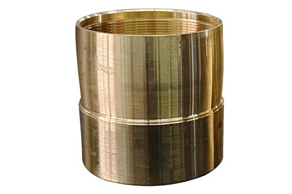
CNC Milling uses a rotating cutting tool to remove material from a stationary workpiece. It's for creating complex 3D shapes, slots, pockets, and holes. CNC Turning rotates the workpiece against a stationary cutting tool. It's for creating cylindrical or conical shapes like shafts, rods, and bushings. Many complex parts require both processes, often done on a single mill-turn machine.
How do I choose between CNC machining and 3D printing for my part?
Choose CNC machining when you need: Superior strength and material properties (from solid stock), tight tolerances (±0.005" or better), excellent surface finishes, and production in engineering metals. Choose 3D printing (additive manufacturing) when you need: Extremely complex, organic geometries (lattices, internal channels), very low volume (1-2 parts) of complex pieces, rapid form/fit prototypes, or consolidation of many assembled parts into one.
What file format should I send to a machine shop for a quote?
Always send a 3D CAD file in a neutral format like STEP (.stp) or IGES (.igs) along with a 2D engineering drawing (.pdf or .dwg). The 3D model defines the geometry, while the 2D drawing specifies critical dimensions, tolerances, materials, finishes, and notes. Providing both prevents ambiguity and ensures an accurate quote.
Can a CNC machine make a part from my hand-drawn sketch?
Not directly. CNC machines require a digital 3D model to generate toolpaths. However, a skilled machine shop can often take a dimensioned sketch or even a physical sample, reverse-engineer it to create a CAD model, and then machine it. This adds significant time and cost compared to starting with a ready-made CAD file.
Contact Yigu Technology for Custom Manufacturing.
At Yigu Technology, we transform your designs into high-quality, precision CNC machined products. We combine advanced multi-axis machining capabilities with deep engineering expertise to deliver parts that meet your exact specifications for performance, durability, and budget.
Our process begins with a collaborative review of your design. Our engineers provide constructive Design for Manufacturability (DfM) feedback to optimize your part for efficient production without compromising its intent. We manage the entire workflow—from material selection and CAM programming to precision machining, post-processing, and rigorous quality inspection—ensuring a seamless experience and a superior final product.
Ready to bring your project to life with precision CNC machining? Contact Yigu Technology today to discuss your requirements and receive a detailed, transparent quote. Let's build something exceptional together.