Introduction
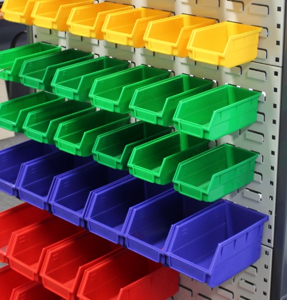
Injection moulding is a widely used manufacturing process for producing plastic parts with high precision and efficiency. The design of the injection mould directly influences product quality, cost, and production efficiency. A well-designed mould ensures dimensional accuracy, reduces defects, and increases productivity.
Poor mould design has significant consequences. According to the Society of Plastics Engineers, about 30 percent of product quality issues in injection moulding are directly related to mould design flaws. In automotive applications, poorly designed moulds lead to warping, shrinkage, or surface defects—affecting both aesthetics and safety.
Optimized design also reduces costs. One consumer electronics company reduced material usage by 15 percent and shortened production cycles by 20 percent after optimizing their mould design—resulting in substantial savings.
This guide explores the key elements of injection mould design, helping you achieve craftsmanship that delivers quality, efficiency, and cost-effectiveness.
What Are the Key Elements in Injection Mould Design?
Material Selection
Plastic Materials: Different plastics offer distinct properties.
| Material | Key Properties | Typical Applications |
|---|---|---|
| ABS | Impact resistance, dimensional stability, easy processability; heat-deflection 90–110°C | Automotive interiors, electronic housings |
| PP (Polypropylene) | Chemical resistance, low density (0.9 g/cm³), heat resistance; melting point 160–170°C | Food containers, automotive bumpers, industrial packaging |
| PC (Polycarbonate) | Outstanding impact strength, high heat resistance (130°C+), excellent optical properties | Eyewear lenses, automotive headlamp lenses, electronic displays |
Choose materials based on intended use, mechanical requirements, heat resistance, chemical resistance, and cost. For high-temperature applications, PC or heat-resistant PP grades are suitable. For cost-sensitive applications where high strength is not critical, ABS may be appropriate.
Mold Materials: Steel is the most common mold material.
| Steel Type | Properties | Applications |
|---|---|---|
| P20 | Good machinability, hardness 30–42 HRC, toughness | Medium-volume production (toys, simple housings) |
| 718H | Higher hardness (35–40 HRC), better polishing properties | High-end electronics housings, complex shapes requiring smooth surfaces |
| S136 | Excellent corrosion resistance, high-quality polishing; hardness 50+ HRC after heat treatment | Medical devices, food-contact products, transparent plastic parts |
Material choice impacts mold lifespan and product quality. Wear-resistant, hard steels provide longer mold life—reducing replacement frequency and lowering long-term production costs. However, these steels cost more, so evaluate production volume and product requirements carefully.
How Does Gate Design Affect Product Quality?
Types of Gates
| Gate Type | Size | Location | Advantages | Disadvantages | Best For |
|---|---|---|---|---|---|
| Side Gate | Width 1–10 mm, thickness 0.5–2 mm | Side of cavity at parting line | Easy to process and modify; simple gate removal | Visible gate marks; may cause weld lines | Medium to large products (boxes, simple toys) |
| Point Gate | Diameter 0.5–2 mm | Various positions, often centered on flat areas | Small, less visible gate marks; automatic breakage for automation; better flow control | High pressure loss; complex three-plate mold structure | Small, high-precision products (electronic components, buttons) |
| Submarine Gate (Latent) | Similar to point gate; slanted channel | Hidden in mold, entering from inner or less-visible surface | Hidden gate; no appearance impact; automatic breakage | Difficult to machine slanted channel; risk of blockage | Aesthetic-critical products (cosmetic containers, high-end housings) |
Gate Location
Gate location profoundly impacts plastic flow and product quality. An inappropriate location causes defects. If placed too far from thick-walled sections, plastic may not fill properly—resulting in short shots.
For a rectangular box, a corner gate causes uneven flow. Sides filling later cool and shrink at different rates than earlier-filling sides, causing warping. A central gate or multiple evenly distributed gates achieve balanced filling, reducing weld lines and air traps that weaken product strength and affect appearance.
How Does Runner System Design Impact Production?
Runner Types and Sizes
Circular runners offer the lowest flow resistance due to the smallest perimeter-to-cross-sectional-area ratio. For high-volume production of small ABS parts, a circular runner with 8–12 mm diameter may be used.
Trapezoidal runners are easier to machine in single-sided operations. Flow resistance is higher than circular. For lower-viscosity plastics like PP, a trapezoidal runner with top width 10–15 mm, bottom width 6–10 mm, and height 4–6 mm may be suitable.
Runner size affects flow resistance and pressure loss. Larger diameters reduce flow resistance but increase material usage and cooling times. A common formula for runner diameter:
D = 0.2654 × W^0.5 × L^0.25
Where W = plastic part weight, L = runner length.
Balanced Runner System
A balanced runner system ensures each cavity in a multi-cavity mold fills evenly. Unbalanced systems cause variations in part dimensions, density, and surface finish.
To achieve balance, make runner lengths equal to each cavity. In a four-cavity square pattern, symmetric runners with equal-length sub-runners achieve balance. Adjust cross-sectional areas according to plastic volume required for each cavity, ensuring uniform pressure drop and consistent flow rate across cavities.
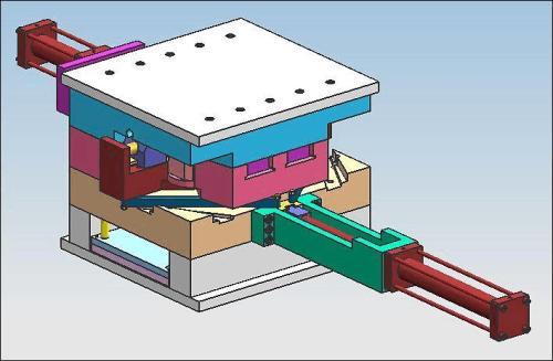
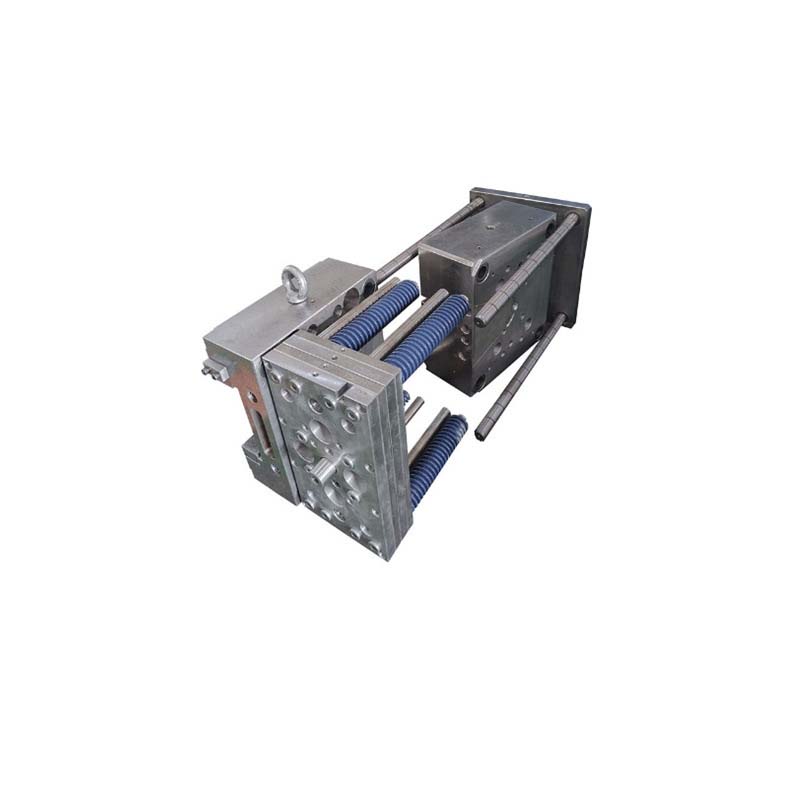
What Mould Structure and Component Design Considerations Exist?
Cavity and Core Design
The cavity forms the product’s outer shape; the core forms internal features.
Draft angle (demolding slope) is essential for easy product removal. For most plastics, 0.5–2 degrees is recommended. For a 50 mm high plastic box, a 1-degree draft on inner and outer walls ensures smooth demolding.
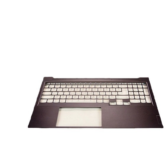
Surface roughness directly impacts product appearance. High-gloss products like mobile phone housings require mirror-like finishes with surface roughness (Ra) below 0.05 μm—achieved through precision machining and polishing. For products requiring textured surfaces for grip, roughness can be adjusted accordingly.
Ejection System Design
Common ejection methods include:
- Ejector pins: Small cylindrical rods at strategic locations. Simple, easy to install and maintain. For small plastic buttons, pins with 1–3 mm diameter work. May leave visible marks if improperly located.
- Ejector blocks: Larger flat components for products with large flat surfaces or irregular shapes. Provide even force distribution—preventing warping in flat panels.
- Stripper plate ejection: Large plate moving as a single unit to push products off the core. Suitable for complex shapes or parts difficult to eject with pins or blocks.
Consider ejection position and force distribution. Position ejectors away from thin-wall areas to avoid damage. Distribute ejection force uniformly—calculate required force based on product surface area contacting cavity/core, then distribute evenly across ejection points.
Cooling System Design
Efficient cooling reduces cycle time and prevents defects like warping and shrinkage.
Channel layout: Cooling channels should be as close as possible to cavity and core surfaces—typically 10–15 mm away—for efficient heat transfer while maintaining structural integrity.
Flow rate impact: Increasing water flow rate from 0.5 L/min to 1.5 L/min can reduce cooling time by about 20 percent.
Water temperature impact: Lowering water temperature from 30°C to 20°C can reduce cooling time by 15–20 percent while improving dimensional stability. However, avoid setting temperatures too low to prevent condensation on mould surfaces, which affects product quality.
How Do You Optimize the Overall Design Process?
Simulation and Analysis
Mould flow analysis software predicts plastic flow patterns, identifying potential issues—air traps, weld lines, uneven filling—before manufacturing. This enables design adjustments without costly physical trials.
Design for Manufacturability (DFM)
Consider manufacturability during design:
- Avoid undercuts that require complex side actions when possible
- Design for standard tool sizes to reduce costs
- Ensure adequate steel thickness around cavities to prevent deflection
- Provide sufficient clearance for cooling channels
Iterative Refinement
Design refinement based on trial results improves quality. After initial trials, inspect parts for defects and adjust gate locations, runner sizes, cooling channel layouts, or ejection systems accordingly.
Yigu Technology’s Perspective
As a custom supplier of non-standard plastic and metal products, we emphasize design optimization as the foundation of successful injection moulding.
Material expertise: We help clients select plastics and mould steels matched to application requirements—heat resistance, chemical exposure, production volume, and surface finish needs.
Design capabilities: Using advanced CAD/CAM and simulation software, we predict flow patterns, identify potential defects, and optimize gate locations, runner systems, and cooling layouts before manufacturing begins.
Process knowledge: Our experience across industries—automotive, medical, electronics—enables us to anticipate challenges and incorporate solutions into the design phase.
Quality focus: Rigorous design reviews and trial iterations ensure moulds produce consistent, high-quality parts throughout their service life.
Conclusion
Injection mould design is a complex process requiring deep understanding of materials, flow dynamics, and mechanical principles. Material selection—both plastic and mould steel—determines product performance and tool life. Gate design and runner systems control plastic flow, preventing defects like short shots, weld lines, and air traps. Balanced runner systems ensure consistent quality across multi-cavity molds.
Cavity and core design with proper draft angles and surface finishes enable smooth demolding and desired product appearance. Ejection systems must distribute force evenly to prevent damage. Cooling systems reduce cycle times and prevent warping.
By carefully optimizing these elements, manufacturers achieve injection mould craftsmanship that delivers high-quality products, improved efficiency, and reduced costs. As technology advances, continued innovation in design tools and processes will further expand what is possible.
FAQ
What is the most important factor in injection mould material selection?
The most important factor depends on product requirements. For high-temperature resistance, the plastic material’s heat resistance is critical. For the mould material, production volume and surface finish requirements determine whether wear-resistant or highly polished steel is needed.
How can I tell if my gate location is correct?
A correct gate location results in even plastic flow, minimal weld lines, and no air traps. Conduct trial injections and inspect products for defects. Use simulation software to predict flow patterns and identify potential issues before actual production.
Why is a balanced runner system necessary in a multi-cavity mold?
A balanced runner system ensures each cavity fills evenly, producing consistent product quality—uniform dimensions, density, and surface finish—across all cavities. Without balance, some cavities fill faster or more completely than others, causing part variations and potential defects.
Contact Yigu Technology for Custom Manufacturing
Looking for expert guidance on injection mould design and manufacturing? Yigu Technology specializes in custom non-standard plastic and metal products. Our team combines design expertise with precision manufacturing to deliver moulds that perform.
Reach out today to discuss your next project. Let us help you achieve optimal injection mould craftsmanship.