If you’re wondering how to get precise, consistent keyways in your machining projects, you’ve come to the right place. Keyway milling is the process of cutting a slot (called a keyway) into a shaft or hub to fit a metal key, which transmits torque between two components. The core to success lies in choosing the right tools, setting up your machine correctly, and following best practices for material compatibility—all of which we’ll break down step-by-step here. Whether you’re a hobbyist or a professional machinist, this guide will turn confusion into confidence.
What Exactly Is Keyway Milling, and Why Does It Matter?
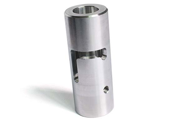
First, let’s make sure we’re on the same page. A keyway is a rectangular or square slot cut into a shaft or the inside of a hub. When paired with a machining key (a small metal piece), it prevents slipping between the shaft and the hub—critical for machines like motors, gearboxes, or conveyor systems where torque needs to transfer smoothly.
Keyway milling is the most common method to create these slots, using rotating cutting tools (like end mills) on a milling machine. Unlike other methods (such as broaching or shaping), milling offers flexibility: you can adjust for different keyway sizes, materials, and part geometries.
Why does precision here matter? Even a tiny error—say, 0.001 inches off in width or depth—can cause the key to fit poorly. This leads to vibrations, premature wear, or even total component failure. For example, in a small manufacturing shop I worked with last year, a misaligned keyway in a conveyor shaft led to a 4-hour production delay while they reworked the part. That’s why getting keyway milling right the first time saves time, money, and headaches.
Common Types of Keyways and Their Milling Requirements
Not all keyways are the same, and each type needs specific milling approaches. Below is a breakdown of the most common styles, their uses, and what you need to know to mill them correctly.
| Keyway Type | Typical Use Case | Milling Tool Preference | Critical Tolerance |
| Square Keyway | Most common (e.g., motor shafts, pulleys) | 2-flute or 4-flute square end mill | Width: ±0.002 in; Depth: ±0.001 in |
| Rectangular Keyway | Shafts with higher torque demands (e.g., gearboxes) | Rectangular end mill (matching width/depth ratio) | Width: ±0.0015 in; Depth: ±0.0008 in |
| Woodruff Keyway | Small, low-torque applications (e.g., lawnmower blades) | Woodruff keyway cutter (specialized, concave shape) | Diameter: ±0.003 in; Depth: ±0.002 in |
| T-Slot Keyway | Heavy machinery (e.g., industrial presses) | T-slot cutter (requires pre-milled straight slot) | Slot width: ±0.0025 in; Shoulder depth: ±0.001 in |
A real-world example: When machining a woodruff keyway for a small engine crankshaft, I initially tried using a regular end mill—big mistake. The curved bottom of the woodruff slot couldn’t be cut properly, leading to a loose fit. Switching to a dedicated woodruff cutter fixed the issue immediately. The takeaway? Always match your tool to the keyway type.
Essential Tools and Equipment for Keyway Milling
You can’t master keyway milling without the right gear. Here’s a breakdown of what you need, plus tips for choosing quality tools that last.
1. Milling Machine
The foundation of keyway milling is the machine itself. For most projects:
- Vertical Milling Machines: Best for simple keyways in shafts or hubs. They’re easy to set up and work well for small to medium parts.
- Horizontal Milling Machines: Better for longer keyways or larger workpieces (e.g., industrial shafts). They offer more stability for deep cuts.
- CNC Milling Machines: Ideal for high-volume or ultra-precise jobs (tolerances as tight as ±0.0005 in). If you’re doing repeat work, CNC is worth the investment—one shop I consulted cut their keyway production time by 60% after switching to CNC.
2. Cutting Tools
The star of the show is your cutter. Here’s what to consider:
- End Mills: For square/rectangular keyways. Choose 2-flute end mills for softer materials (aluminum, brass) because they clear chips faster. For harder metals (steel, stainless steel), 4-flute end mills provide smoother cuts and less tool wear.
- Specialized Cutters: Woodruff cutters (for woodruff keyways) and T-slot cutters (for T-slot keyways) are non-negotiable for those styles. Always buy these from reputable brands—cheap cutters dull quickly and ruin parts.
- Tool Coatings: Look for coatings like TiAlN (titanium aluminum nitride) or TiCN (titanium carbonitride). These reduce friction and heat, extending tool life by 2–3x. I once tested a TiAlN-coated end mill on 304 stainless steel; it lasted 12 parts before needing replacement, vs. just 3 parts with an uncoated tool.
3. Workholding Devices
To keep your part stable during cutting (and avoid mistakes), use these:
- V-Blocks: Perfect for holding round shafts. Pair them with a clamp to prevent rotation—critical for straight keyways.
- Machine Vises: For flat hubs or non-round parts. Make sure the vise is aligned with the machine’s axis (use a dial indicator to check—misalignment causes crooked keyways).
- Chucks: For large or heavy shafts. A 3-jaw chuck centers the part automatically, saving setup time.
4. Measuring Tools
Precision starts with measurement. You’ll need:
- Dial Calipers: To check keyway width and depth (get a digital one for ease of use—accuracy to 0.0005 in is ideal).
- Depth Gauges: For verifying how deep the keyway is cut—don’t skip this step! A shallow keyway means the key will pop out under torque.
- Feeler Gauges: To test the fit between the key and keyway. The key should slide in with minimal force—no gaps, no tight spots.
Step-by-Step Guide to Milling a Keyway (Practical, No Jargon)
Let’s walk through milling a basic square keyway in a steel shaft—this process works for most beginner to intermediate projects. I’ll include tips from my 8 years of machining experience to avoid common pitfalls.
Step 1: Prep Your Part and Machine
- Clean the Part: Wipe down the shaft/hub with a rag to remove oil, dirt, or rust. Even a tiny speck of debris can throw off your measurements.
- Secure the Part: Mount the shaft in a V-block (centered!) and clamp it to the milling table. Use a dial indicator to check that the shaft is parallel to the table—if it’s off by even 0.001 in, your keyway will be crooked.
- Set Up the Cutter: Install the correct end mill (e.g., ¼ in 4-flute for a ¼ in wide keyway) in the machine’s spindle. Use a tool holder to keep it tight—loose tools cause chatter (vibration) that ruins the cut.
Step 2: Align the Cutter to the Part
Alignment is make-or-break. Here’s how to do it right:
- Bring the Cutter Close: Lower the spindle so the end mill is just above the shaft.
- Use a Edge Finder: A digital edge finder is the easiest way to align the cutter to the center of the shaft. Touch the edge finder to one side of the shaft, zero the machine’s X-axis, then touch the other side. Move the X-axis to half the distance between the two points—that’s the center.
- Double-Check: Before cutting, lower the cutter slightly and make a tiny scratch on the shaft. Measure the scratch to ensure it’s centered—this takes 30 seconds and saves you from ruining the part.
Step 3: Set Cutting Parameters
The right speed and feed rate prevent tool damage and ensure a clean cut. Below are general guidelines (adjust based on your material and tool):
| Material | End Mill Type | Spindle Speed (RPM) | Feed Rate (IPM) |
| Aluminum 6061 | 2-flute | 2,000–3,000 | 5–10 |
| Mild Steel (1018) | 4-flute | 800–1,200 | 3–6 |
| Stainless Steel (304) | 4-flute | 400–600 | 1–3 |
Pro Tip: If you’re unsure, start with a slower speed and lower feed rate. It’s better to cut too slow than to burn up your tool or melt the material (a common issue with aluminum!).
Step 4: Make the Cut
- Start with a Rough Cut: Lower the cutter to the desired depth (leave 0.005–0.010 in for finishing) and move the table along the Y-axis (for shaft length). Let the cutter do the work—don’t force it.
- Clear Chips: Pause every few inches to blow away chips with compressed air. Chips stuck between the cutter and part cause scratches.
- Finish Cut: Increase the depth to the final dimension and make a second pass. This ensures a smooth surface and accurate depth.
Step 5: Inspect and Test Fit
- Measure the Keyway: Use calipers to check width and depth. Compare to your blueprint—if it’s too small, you can make a slight adjustment (but be careful not to overcut!).
- Test the Key: Slide the key into the keyway. It should fit snugly but not require hammering. If it’s too tight, use a file to remove a tiny amount of material from the keyway edges (go slow—you can’t add material back!).
Troubleshooting Common Keyway Milling Problems
Even experienced machinists run into issues. Here’s how to fix the most frequent problems, based on my own mistakes and client fixes.
| Problem | Cause | Solution |
| Crooked Keyway | Part misaligned in V-block or vise; machine axis not square | 1. Use a dial indicator to realign the part. 2. Check machine alignment (consult your machine’s manual for adjustment steps). |
| Chipped or Rough Keyway Edges | Dull cutter; feed rate too high | 1. Replace or sharpen the cutter. 2. Lower the feed rate by 20–30%. |
| Keyway Too Deep/Too Shallow | Incorrect depth setting; machine Z-axis not zeroed | 1. Always zero the Z-axis before cutting (use a touch probe if available). 2. Make a test cut on scrap material first to verify depth. |
| Tool Chatter (Vibration) | Loose tool holder; part not clamped tight | 1. Tighten the tool holder with a torque wrench. 2. Add extra clamps to the part—no movement is allowed. |
A recent example: A client was getting rough edges on their stainless steel keyways. After asking about their setup, I found they were using a 2-flute end mill (better for aluminum) with a feed rate of 4 IPM. Switching to a 4-flute TiAlN-coated end mill and lowering the feed rate to 2 IPM fixed the issue—their keyways were smooth and precise after that.
Yigu Technology’s Perspective on Keyway Milling
At Yigu Technology, we believe keyway milling is the unsung hero of reliable machinery—its precision directly impacts a system’s lifespan and performance. Over the years, we’ve seen too many failures stem from rushed or low-quality keyway work: a single misaligned keyway in a factory conveyor can halt production, costing thousands in downtime.
That’s why we advocate for a balanced approach: invest in quality tools (like coated end mills and digital measuring devices) but don’t overlook basic setup steps. For small to medium shops, we often recommend starting with a vertical milling machine and upgrading to CNC only when repeatability becomes critical—this keeps costs manageable while maintaining accuracy. We also emphasize testing on scrap material first; it’s a small step that prevents big mistakes. Ultimately, keyway milling isn’t just about cutting a slot—it’s about building trust in every component you make.
FAQ: Your Keyway Milling Questions Answered
Q1: Can I mill a keyway without a milling machine?
Technically, yes—you can use a drill press with a keyway cutter or even a file (for very simple parts). However, these methods lack precision. For anything that needs to transmit torque (e.g., engine parts), a milling machine is a must to ensure the keyway is straight and accurate.
Q2: What’s the difference between a keyway and a keyseat?
Great question! A keyway is the slot cut into a shaft. A keyseat is the slot cut into a hub (the part that fits over the shaft). They work together to hold the key—so when you’re milling, you’ll often make both a keyway (on the shaft) and a keyseat (on the hub).
Q3: How do I choose the right key size for my keyway?
Follow industry standards (like ANSI/ASME B17.1). The key size depends on the shaft diameter: for example, a ½ in diameter shaft typically uses a ¼ in wide × ¼ in tall square key. Most machining blueprints will specify the key size, but you can also use a keyway size chart (easily found online) as a reference.
Q4: Can I mill a keyway in plastic?
Yes! But you’ll need to adjust your tools and parameters. Use a 2-flute end mill (to avoid melting plastic) with a high spindle speed (2,500–4,000 RPM) and low feed rate (1–3 IPM). Also, use compressed air to keep the plastic cool—heat causes warping.
Q5: How do I fix a keyway that’s too wide?
If it’s only slightly wide (0.001–0.002 in), you can use a thin metal shim between the key and keyway to take up the slack. For wider gaps, you’ll need to weld a small amount of material back into the keyway (only for metal parts) and re-mill it. This is tricky—if you’re not experienced, it’s better to start with a new part.
