Introduction
In modern manufacturing, precision is not a luxury—it is a necessity. Aerospace components demand tolerances measured in microns. Medical implants require flawless surfaces. Automotive parts must perform reliably under extreme conditions. The companies that master precision become essential partners to industries where failure is not an option.
CNC Machining Co. Ltd has emerged as a leader in this space, pioneering precision-crafted manufacturing through advanced technology, skilled expertise, and rigorous quality systems. From engine components that improve fuel efficiency to surgical instruments with micron-level accuracy, the company’s impact spans industries. This guide explores how CNC Machining Co. Ltd achieves precision-crafted excellence—and what makes it a trusted partner for the world’s most demanding manufacturers.
What Core Competencies Define CNC Machining Co. Ltd?
Precision manufacturing requires more than machines. It demands a combination of advanced equipment, skilled people, and proven processes.
Advanced Equipment and Technology
CNC Machining Co. Ltd operates a fleet of state-of-the-art machinery designed for high-precision work.
| Machine Type | Example | Capability |
|---|---|---|
| 5-axis machining centers | DMG MORI DMU 75 monoBLOCK | Positioning accuracy ±0.001 mm; complex geometries in one setup |
| 4-axis machining centers | Multi-axis linkage | 30–50% higher efficiency than 3-axis; reduces setups |
| Turning-milling compound centers | Integrated turning and milling | Single machine completes multiple operations; eliminates transfer errors |
5-axis machining is particularly transformative. By moving the workpiece and cutting tool simultaneously along five axes, these machines produce intricate shapes in a single setup. For aerospace engine components with tolerances measured in microns, this capability is essential.
Skilled Workforce
Technology alone does not guarantee precision. Skilled people make the difference.
| Role | Experience | Key Skills |
|---|---|---|
| Engineers | 10+ years average | CAD/CAM software, process optimization |
| Technicians | 10+ years average | Machine operation, tool selection, problem-solving |
Aerospace case study: A customer required a complex titanium alloy component with extremely tight tolerances. Engineers used advanced CAD/CAM software to design optimized tool paths, accounting for titanium’s high strength and tendency to overheat. After careful programming and multiple test runs, they achieved dimensional accuracy of ±0.002 mm—exceeding the customer’s requirements.
Medical device case study: A miniaturized surgical instrument required micron-level precision. Technicians worked with extremely small tools under high-magnification microscopes. Their knowledge of materials and processes guided selection of cutting fluids and tool coatings. The result: mass production with a defect rate below 0.5%—setting a new industry standard.
What Does the Precision-Crafted Process Look Like?
The journey from design to finished part follows a meticulously planned sequence.
Product Design
The process begins with in-depth design using advanced CAD software like SolidWorks.
- 3D modeling: Creates detailed digital representations
- Simulation: Tests designs under operating conditions
- Optimization: Considers material properties, heat dissipation, mechanical stress
Example: When designing an automotive engine component, engineers simulate operating conditions to optimize for functionality and manufacturability before any metal is cut.
Programming
Once the design is finalized, CAM software (Mastercam, NX) generates CNC programs.
- Tool path optimization: Calculates most efficient cutting routes
- Parameter selection: Sets speeds, feeds, and depths for specific materials
- Simulation: Verifies programs before running on machines
For high-precision medical implants, programming must be extremely accurate to ensure proper fit and function.
Machining
With programs in place, CNC machines begin production.
- 5-axis machining: For complex geometries, single-setup production
- Controlled parameters: Spindle speed, feed rate, depth of cut carefully managed
- Material-specific strategies: Titanium requires different parameters than aluminum
Example: When machining high-strength titanium for aerospace, spindle speeds are carefully controlled to avoid overheating and maintain material integrity.
Quality Inspection
Every part undergoes rigorous inspection after machining.
| Inspection Type | Method | Accuracy |
|---|---|---|
| Visual | Surface defects, burrs | N/A |
| Dimensional | CMM (Coordinate Measuring Machine) | ±0.0001 mm |
| Surface finish | Profilometer | Ra values |
How Does CNC Machining Co. Ltd Ensure Quality?
Quality control is embedded at every stage of manufacturing.
Coordinate Measuring Machines (CMMs)
CMMs measure dimensions with accuracy up to ±0.0001 mm.
- Applications: Hole diameters, surface flatness, angular features
- Process: Data compared to design specifications
- Response: Immediate halt and corrective action if deviations detected
Statistical Process Control (SPC)
SPC monitors production in real-time, detecting trends before quality issues occur.
- Data collection: Machining parameters, part dimensions
- Control charts: X-bar charts track average dimensions; R-charts track variation
- Action: Out-of-control conditions trigger investigation and correction
Raw Material Control
Only materials meeting the highest quality standards are accepted for production. This ensures final products maintain consistent quality and reliability.
What Success Stories Demonstrate Capability?
Real-world examples show how precision manufacturing translates to customer value.
Automotive Industry: Engine Components
Challenge: Improve engine performance and fuel efficiency through precision components.
Solution: CNC Machining Co. Ltd produced cylinder heads with average dimensional accuracy of ±0.003 mm.
Results:
| Performance Indicator | Before | After |
|---|---|---|
| Fuel Efficiency | 25 mpg | 27 mpg (+8%) |
| Power Output | 150 hp | 168 hp (+12%) |
Additional success: Transmission gears with surface roughness below 0.2 μm reduced friction and wear. For a luxury car brand, this led to a 30% reduction in gear-related noise—enhancing comfort and luxury features.
Aerospace Industry: Turbine Blades and Structural Components
Challenge: Manufacture components that withstand extreme temperatures and mechanical stresses with absolute reliability.
Solution: Turbine blades machined from advanced superalloys with precision to ±0.001 mm.
Results:
- Engine efficiency increased by 5%
- In-flight engine shutdowns reduced by 40%
- Significant fuel savings for airlines
Structural components: Wing spars and fuselage frames machined from high-strength aluminum and titanium alloys.
Results:
- Aerodynamic efficiency improved by 3%
- Aircraft range increased by 100 nautical miles
- Expanded route networks and revenue for airlines
What Industries Benefit from Precision-Crafted Manufacturing?
CNC Machining Co. Ltd serves industries where precision is critical.
| Industry | Applications | Precision Requirements |
|---|---|---|
| Aerospace | Turbine blades, structural components, engine parts | ±0.001 mm, full traceability |
| Automotive | Cylinder heads, transmission gears, engine components | ±0.003 mm, surface finish <0.2 μm |
| Medical | Surgical instruments, implants, diagnostic equipment | Micron-level accuracy, biocompatibility |
| Industrial | Hydraulic components, machine parts, tooling | Application-specific tolerances |
Conclusion
CNC Machining Co. Ltd has established itself as a pioneer in precision-crafted manufacturing through a combination of advanced equipment, skilled workforce, and rigorous quality systems. Its 5-axis machining centers, turning-milling compound machines, and CMM inspection achieve tolerances that meet the most demanding industry requirements.
Success stories across automotive and aerospace demonstrate the impact of precision manufacturing—improved fuel efficiency, increased power output, extended range, and enhanced reliability. With a defect rate below 0.5% for critical medical components and the ability to handle both small-batch and high-volume production, the company has become an essential partner for leading manufacturers worldwide.
In an era where precision defines competitiveness, CNC Machining Co. Ltd continues to set the standard.
FAQs
What types of materials can CNC Machining Co. Ltd work with?
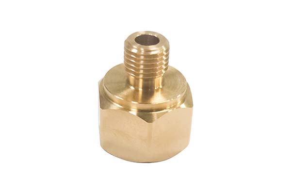
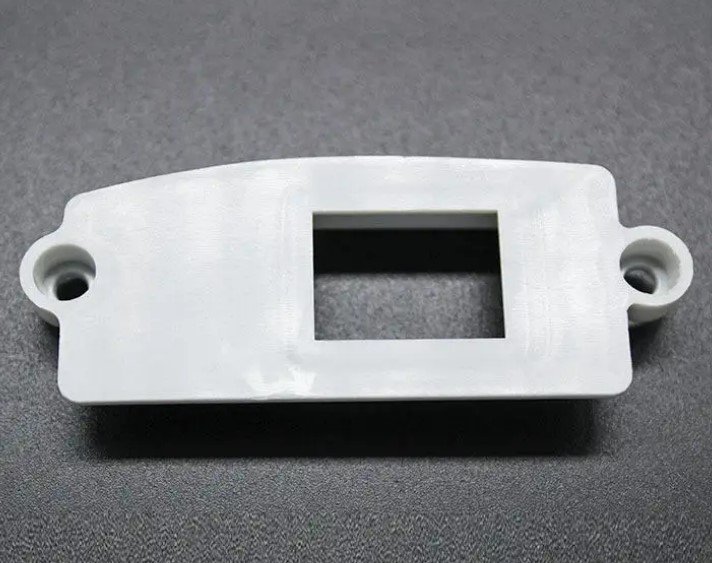
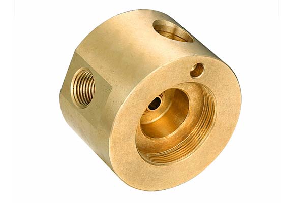
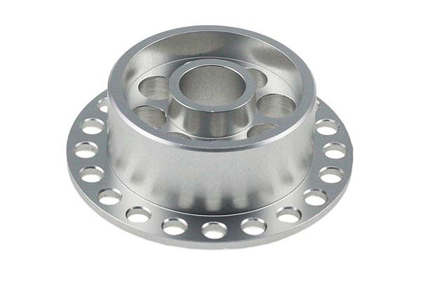
The company works with a wide range of materials, including metals (aluminum, stainless steel, brass, titanium) and plastics (ABS, nylon, acrylic, PEEK). Skilled engineers select the most suitable material for each application based on mechanical properties, thermal requirements, and regulatory standards.
How does CNC Machining Co. Ltd ensure quality?
Quality is ensured through a multi-step process: strict raw material inspection, statistical process control (SPC) during manufacturing to monitor and adjust parameters in real-time, and final inspection using high-precision CMMs (accurate to ±0.0001 mm) to verify every part against design specifications.
Can CNC Machining Co. Ltd handle both small-batch and large-batch production?
Yes. Advanced CNC machines and efficient processes allow quick changeovers for small-batch production, ensuring flexibility. For large-batch production, high-capacity equipment and streamlined production lines maintain consistent quality while meeting tight deadlines.
What industries does CNC Machining Co. Ltd serve?
The company serves aerospace (turbine blades, structural components), automotive (engine components, transmission parts), medical (surgical instruments, implants), and industrial (hydraulic components, tooling) sectors. Each industry has specific precision and quality requirements that the company’s processes are designed to meet.
What is the typical lead time for custom parts?
Lead times vary based on part complexity, material, and quantity. Prototypes often require 3–7 days. Production runs typically range from 2–6 weeks. Rush services are available for urgent projects.
Contact Yigu Technology for Custom Manufacturing
At Yigu Technology, we share the commitment to precision that defines CNC Machining Co. Ltd. With 15 years of experience, advanced 5-axis machining capabilities, and ISO 9001 certification, we deliver components that meet the most demanding specifications.
Our team combines technical expertise with transparent communication—from design optimization to final inspection. Whether you need aerospace components, medical devices, or industrial parts, we have the capabilities and commitment to deliver precision and reliability. Contact us today to discuss your custom manufacturing needs.