Introduction
Milling metals is a cornerstone of manufacturing. From automotive engine blocks to aerospace turbine blades, milling shapes the critical components that power modern industry. But excelling at metal milling is not simple. Many users struggle to choose between climb milling and conventional milling for different materials, leading to poor surface finish or rapid tool wear. Selecting the right cutting tools for tough metals like titanium or nickel-based alloys often feels like a guessing game. Setting optimal milling parameters—cutting speed, feed rate, depth of cut—can seem like trial and error.
This comprehensive guide addresses these pain points. We will cover milling processes, metal materials, machine selection, cutting tools, parameter optimization, surface finish, and advanced techniques. Whether you are machining aluminum or Inconel, you will find practical insights to achieve precision and efficiency.
What Milling Processes Should You Choose?
Basic Milling Methods
Conventional milling (up milling) and climb milling (down milling) differ in cutter rotation direction relative to workpiece feed. In conventional milling, the cutter rotates against the feed direction, creating a rubbing action at the start of the cut. This can cause poor surface finish and increased tool wear.
In climb milling, the cutter rotates with the feed direction. The result is a smoother cut, less tool wear, and better surface finish. For aluminum, climb milling can reduce tool wear by 30–40% compared to conventional milling. However, climb milling requires machines with minimal backlash—older manual machines may not be suitable.
Face milling creates flat surfaces using a face mill with multiple cutting inserts. It can achieve surface roughness (Ra) as low as 1.6 μm on steel. End milling uses an end mill to create slots, pockets, and contours. It is versatile for both 2D and 3D machining operations.
Specialized Milling Processes
High-speed milling is a productivity game-changer. Using spindle speeds of 10,000–60,000 RPM and fast feed rates, it reduces machining time by 50–70% compared to conventional milling. For example, high-speed milling a 50 mm x 50 mm steel block with a 10 mm end mill takes about 2 minutes at 30,000 RPM—versus 5–6 minutes at 5,000 RPM.
Profile milling creates complex 2D or 3D contours, essential for aerospace components with curved surfaces. Step milling creates stepped features with specific depths and widths. Gang milling uses multiple cutters on a single arbor to perform several operations simultaneously, ideal for mass production of parts with multiple features.
| Process | Best For | Key Advantage |
|---|---|---|
| Climb Milling | Most materials, especially aluminum | Smoother finish, less tool wear |
| Conventional Milling | Machines with backlash, roughing | Safer for older equipment |
| High-Speed Milling | Productivity, precision parts | 50–70% cycle time reduction |
| Face Milling | Flat surfaces | Ra 1.6 μm achievable |
What Metal Materials Can You Mill?
Common Metals and Their Properties
Aluminum is one of the easiest metals to mill. Its low hardness (60–100 HB) and high machinability allow high cutting speeds—100–300 m/min with carbide tools. Climb milling is preferred to prevent chip welding.
Steel is more challenging. Carbon steel with hardness 150–250 HB requires cutting speeds of 50–150 m/min. Tool wear is a concern, so sharp tools and appropriate coatings are essential.
Stainless steel combines toughness with work hardening. Cutting speeds of 30–100 m/min are recommended. Sharp tools minimize work hardening. AlTiN-coated carbide extends tool life significantly.
Titanium is high-strength and lightweight but has low thermal conductivity. Heat builds up in the cutting zone, demanding cutting speeds as low as 10–30 m/min and plenty of coolant.
Challenging Metals
Nickel-based alloys (Inconel, Hastelloy) maintain strength at high temperatures but are very difficult to mill. Cutting speeds are often limited to 5–20 m/min. Tool wear is rapid, requiring rigid setups and advanced coatings.
Cast iron is brittle, which makes chip control easier, but its abrasive nature wears tools quickly. Ceramic tools can extend tool life with cutting speeds of 200–400 m/min.
| Metal | Hardness (HB) | Cutting Speed (m/min) | Key Challenge |
|---|---|---|---|
| Aluminum | 60–100 | 100–300 | Chip welding |
| Steel | 150–250 | 50–150 | Tool wear |
| Stainless Steel | 150–300 | 30–100 | Work hardening |
| Titanium | 300–400 | 10–30 | Heat buildup |
| Nickel Alloys | 200–400 | 5–20 | Extreme tool wear |
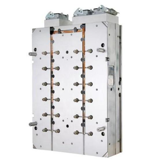
What Milling Machines Deliver Results?
Types of Milling Machines
Vertical milling machines have a vertical spindle, making them ideal for face milling, end milling, and die sinking. They are compact and versatile, suitable for small to medium workpieces.
Horizontal milling machines have a horizontal spindle, better for heavy-duty milling, gang milling, and cutting deep slots. They excel at production runs where multiple cuts are needed.
CNC milling machines have revolutionized metal milling with precision and automation. They perform complex operations with minimal human intervention, achieving tolerances of ±0.001 mm. A 3-axis CNC mill handles most 2.5D parts. A 5-axis CNC mill handles complex 3D shapes like turbine blades.
Manual milling machines are still used for small-batch production and prototyping, but precision relies heavily on operator skill.
Special-Purpose Machines
Portal milling machines are large, heavy-duty machines for milling large workpieces—machine beds, structural components. The gantry structure allows the cutter to move over the workpiece.
Universal milling machines can swivel the table, enabling milling of angles and complex shapes. They are useful for tool and die making.
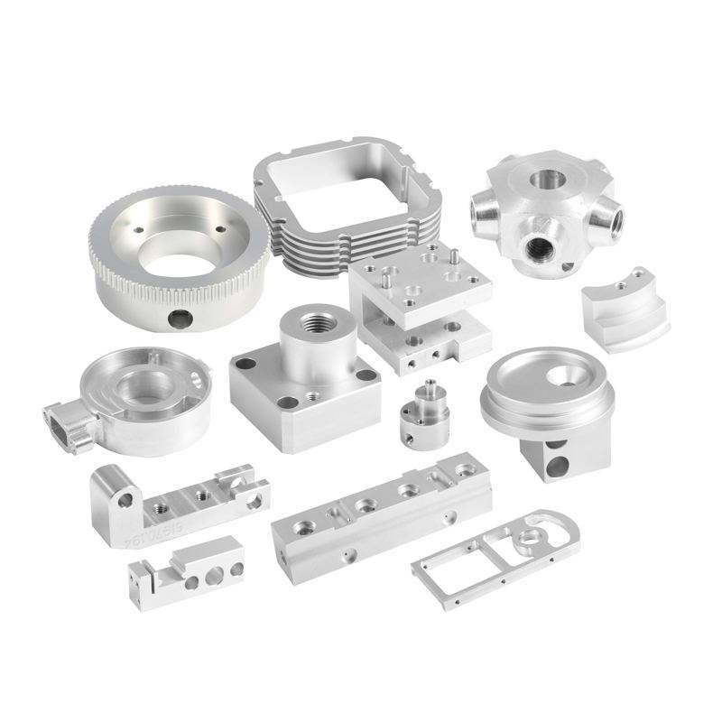
What Cutting Tools Ensure Success?
Types of Cutting Tools
End mills are the most versatile. Flutes run the length of the tool. 2-flute end mills suit aluminum (better chip evacuation). 4-flute end mills are better for steel (more cutting edges).
Face mills use multiple cutting inserts that can be replaced when worn. They are efficient for large flat surfaces.
Tool Materials and Coatings
Carbide tools are harder and more wear-resistant than high-speed steel (HSS). They withstand higher temperatures—1000°C maximum versus 600°C for HSS. Carbide is the standard for CNC milling.
Coated tools—TiN, TiAlN, AlTiN coatings—further improve tool life by reducing friction and wear. An AlTiN-coated carbide end mill can last 2–3 times longer than an uncoated one when milling stainless steel.
Tool Selection Tips
When selecting a cutting tool, consider material, process, and desired surface finish. For high-speed milling of aluminum, a carbide end mill with polished flute surfaces prevents chip welding. For titanium, a cobalt-coated carbide tool with sharp cutting edge and positive rake angle reduces cutting forces and heat.
How Do You Optimize Milling Parameters?
Key Parameters
Cutting speed (m/min) is the speed at which the cutting edge moves relative to the workpiece. It depends on material and tool material. Carbide handles higher speeds than HSS.
Feed rate (mm/min) is the speed at which the workpiece moves relative to the tool. It is calculated by multiplying chip load (mm/tooth) by number of teeth and spindle speed (RPM).
Depth of cut is the distance the tool penetrates in the Z-axis. Width of cut is the amount of tool diameter engaged. For roughing, depth of cut equal to tool diameter is common. For finishing, use 0.1–0.5 mm depth.
Tool overhang should be minimized to reduce deflection, which affects surface finish and accuracy.
Recommended Parameters for Carbide Tools
| Metal | Cutting Speed (m/min) | Feed Rate (mm/min) | Depth of Cut (mm) | Spindle Speed (RPM) for 10mm Tool |
|---|---|---|---|---|
| Aluminum | 100–300 | 500–2000 | 1–5 | 3180–9550 |
| Steel | 50–150 | 200–1000 | 0.5–3 | 1590–4770 |
| Stainless Steel | 30–100 | 100–500 | 0.3–2 | 955–3180 |
| Titanium | 10–30 | 50–200 | 0.2–1 | 318–955 |
| Nickel Alloys | 5–20 | 20–100 | 0.1–0.5 | 159–636 |
How Do You Achieve Desired Surface Finish?
Measuring Surface Finish
Surface roughness is measured using a profilometer, giving an Ra value (arithmetic mean deviation). For most engineering applications, Ra 1.6–6.3 μm is acceptable. Precision parts may require Ra as low as 0.025 μm.
Surface flatness matters for mating components. Tolerances range from ±0.01 mm/m for precision machine beds to ±0.1 mm/m for less critical parts.
Surface defects—cracks, burrs, scratches—can weaken parts and affect performance. Inspection after milling is essential.
Improving Surface Finish
For finishing passes, use high feed rates and low depth of cut. A step-over distance of 10–20% of tool diameter creates a smooth surface.
Sharp tools and adequate coolant reduce surface roughness by minimizing friction and heat-induced damage. For critical surfaces, a finishing pass with a fresh, sharp tool makes a significant difference.
Where Is Milling Applied Across Industries?
Industrial Applications
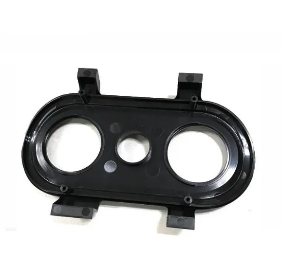
Automotive relies heavily on milling for engine blocks, cylinder heads, and transmission parts. CNC milling machines produce these parts with high precision and repeatability, meeting strict quality standards.
Aerospace uses milling to create lightweight, high-strength components from titanium and aluminum alloys—wing spars, fuselage parts, turbine blades. 5-axis milling enables complex geometries in single setups.
Medical equipment manufacturing uses milling for surgical instruments and implant components, which require high precision and biocompatibility.
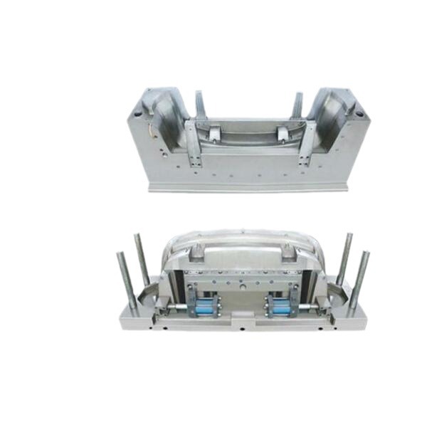
Tool and die making depends on milling to create molds and dies for plastic injection molding and metal stamping.
Other Applications
Prototyping benefits from milling’s ability to quickly produce functional prototypes from metal. Custom machining shops use milling to create one-of-a-kind parts for diverse industries. Research and development uses milling to fabricate experimental components.
What Advanced Techniques Improve Results?
Thread Milling
Thread milling creates internal and external threads. Advantages over tapping include:
- Ability to thread holes with interrupted cuts
- Single tool for different thread sizes
- Better chip control in tough materials
Gear Milling
Gear milling produces gears using specialized cutters. Hob milling is the most common method for large-scale gear production.
Adaptive Milling
Adaptive milling uses real-time feedback to adjust cutting parameters based on material properties and tool condition. It optimizes cutting forces, reduces tool wear, and improves surface finish—ideal for machining complex parts with varying material hardness.
Helical Milling
Helical milling creates holes by moving the tool in a helical path. It eliminates the need for center drills and reduces tool breakage risk. It is especially useful for drilling large holes in tough materials.
Conclusion
Excelling at milling metals requires understanding the interplay between processes, materials, machines, tools, and parameters. The right choices deliver precision, efficiency, and cost-effectiveness.
Climb milling generally produces better surface finish and tool life than conventional milling, provided the machine has minimal backlash. High-speed milling dramatically reduces cycle times for complex parts. Material-specific parameters—cutting speeds 100–300 m/min for aluminum, 5–20 m/min for nickel alloys—balance productivity against tool life.
Tool selection matters. Carbide tools handle higher speeds. AlTiN coatings extend life in stainless steel and titanium. Parameter optimization—feed rates, depths of cut, step-over distances—determines surface finish and dimensional accuracy.
Advanced techniques—thread milling, gear milling, adaptive milling—expand capabilities for complex features and tough materials.
By mastering these elements, manufacturers achieve consistent, high-quality results across the demanding applications that define modern industry.
FAQ
What is the difference between climb milling and conventional milling?
In climb milling, the cutter rotates with the workpiece feed direction, resulting in a smoother cut, less tool wear, and better surface finish. Conventional milling has the cutter rotating against the feed direction, which can cause more tool wear and a rougher surface. Conventional milling is safer for machines with backlash in the feed screws.
How do I choose the right cutting tool for milling stainless steel?
Select a carbide tool with a sharp cutting edge and positive rake angle to minimize work hardening. AlTiN-coated tools reduce friction and tool wear. A 4-flute end mill provides good chip evacuation. A high-helix angle helps clear chips effectively.
What are the benefits of high-speed milling?
High-speed milling increases productivity by reducing machining time 50–70%. It improves surface finish due to smaller chip loads. It reduces heat transfer to the workpiece, minimizing thermal distortion. It enables machining of complex shapes with tight tolerances for aerospace and medical applications.
How do I prevent tool wear when milling titanium?
Use carbide tools with AlTiN or TiAlN coatings that withstand high temperatures. Maintain low cutting speeds (10–30 m/min) to control heat. Use high-pressure coolant (70–100 bar) to cool the cutting zone. Take shallow depths of cut (0.2–1 mm) to reduce cutting forces. Minimize tool overhang to prevent deflection.
What surface finish can I expect when milling aluminum?
With proper parameters—sharp tools, climb milling, finishing passes at high feed rates and low depth of cut—aluminum can achieve Ra 0.4–1.6 μm. For optical or sealing surfaces, polishing after milling can reduce Ra below 0.1 μm.
Contact Yigu Technology for Custom Manufacturing
Need precision milled metal components? Yigu Technology combines advanced CNC milling capabilities with deep material expertise to deliver high-quality parts across aerospace, automotive, medical, and industrial sectors. Our engineers optimize tool selection, cutting parameters, and finishing processes to meet your specifications. Contact us today to discuss your requirements.