What is Metal Injection Molding?
Metal Injection Molding (MIM) is an advanced near-net - shape forming technology that combines the advantages of plastic injection molding technology and traditional powder metallurgy processes. This innovative manufacturing method has revolutionized the production of complex and precise metal components.
At its core, MIM begins with a carefully selected metal powder. This powder is not just any metal powder; it has specific particle size distributions and characteristics tailored to the MIM process. The powder is then mixed with a special binder, usually a polymer - based material. This binder serves two crucial functions. First, it gives the metal powder the flowability necessary to be injected into a mold cavity, much like plastic in traditional plastic injection molding. Second, it holds the metal powder particles together in the desired shape during the initial stages of the process.
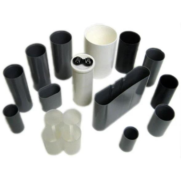
The resulting mixture, a homogeneous blend of metal powder and binder, is referred to as the feedstock. This feedstock is then processed through an injection molding machine. The injection molding stage is where the magic of MIM starts to take shape. Under high pressure, the feedstock is forced into a precision - designed mold cavity. The mold cavity is crafted to the exact dimensions and shape of the final metal component required. This allows for the production of parts with complex geometries, internal features, and high - precision tolerances that would be extremely challenging or even impossible to achieve with traditional metal - working methods.
For example, components with intricate internal channels, fine threads, or undercuts can be easily produced through MIM. Once the injection molding is complete, the green part, which is the molded part consisting of metal powder and binder, is removed from the mold. At this stage, the green part has the basic shape of the final product but is still in a relatively weak and porous state due to the presence of the binder and the spaces between the metal powder particles.
The Process of Metal Injection Molding
1. Feedstock Preparation
The first crucial step in the Metal Injection Molding process is feedstock preparation. This begins with the selection of high - quality metal powder. The metal powder's particle size is a critical factor. Generally, powders with particle sizes in the range of 1 - 50 micrometers are used. For example, in the production of small, high - precision components for the electronics industry, a finer powder with an average particle size of around 5 - 15 micrometers might be chosen. This is because finer powders can result in better surface finish and higher density parts after sintering.
The binder, as mentioned earlier, is equally important. Common binders include wax - based, polymer - based, and thermoplastic materials. The binder content in the feedstock typically ranges from 30% - 60% by volume. It not only provides the necessary flowability for injection but also holds the metal powder particles together during the initial stages of the process. A well - formulated feedstock should have a homogeneous distribution of metal powder in the binder, ensuring consistent properties throughout the part. Any agglomeration of metal powder in the feedstock can lead to defects in the final product, such as porosity or uneven shrinkage during sintering.
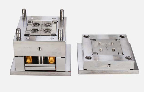
2. Injection Molding
Once the feedstock is prepared, it is fed into an injection molding machine. The injection molding stage involves several key parameters: injection speed, temperature, and pressure.
Injection Speed: The injection speed affects the filling of the mold cavity. A slow injection speed may result in incomplete filling of the mold, especially for complex - shaped parts with thin walls or long flow paths. On the other hand, an overly fast injection speed can cause issues like air entrapment, high shear stress on the feedstock, and even separation of the metal powder from the binder. For a typical MIM part with a medium - sized and moderately complex geometry, an injection speed in the range of 20 - 80 mm/s might be suitable. For example, in the production of a small metal gear with fine teeth, an injection speed of around 40 - 60 mm/s could ensure proper filling of the intricate tooth profiles without causing defects. Research by [Researcher Name] has shown that for Fe - 4Ni alloy MIM parts, an injection speed of 40 mm/s led to better mechanical properties and density compared to other speeds tested.
Injection Temperature: The temperature of the feedstock during injection is also critical. The temperature needs to be high enough to ensure the binder has sufficient fluidity for injection but not too high to cause degradation of the binder or oxidation of the metal powder. For most MIM feedstocks, the injection temperature ranges from 150°C - 250°C. For instance, if the binder is a polymer - based material like polypropylene, the injection temperature might be set around 180°C - 220°C to ensure optimal flow characteristics.
Injection Pressure: Injection pressure is used to force the feedstock into the mold cavity. The required pressure depends on factors such as the complexity of the mold geometry, the viscosity of the feedstock, and the size of the part. Lower - pressure injection (around 5 - 20 MPa) may be sufficient for simple - shaped parts with short flow paths, while high - pressure injection (up to 100 MPa or more) may be necessary for complex, high - precision parts. For a part with internal channels and undercuts, a higher injection pressure might be required to ensure complete filling of all the cavities.
After injection, the mold is cooled to solidify the feedstock, and the green part, which is the initial molded part containing both the metal powder and the binder, is ejected from the mold.
3. Debinding
The green part from the injection molding stage still contains a significant amount of binder. Debinding is the process of removing this binder from the green part. There are several methods of debinding:
Thermal Debinding: In thermal debinding, the green part is heated slowly in a controlled atmosphere. As the temperature rises, the binder decomposes and evaporates. The heating rate is crucial; a too - fast heating rate can cause cracking or distortion of the part due to the rapid expansion and release of the binder. For example, if the binder is a wax - based material, it might start to decompose around 150°C - 250°C, and the entire debinding process could take several hours to ensure a uniform and complete removal of the binder.
Solvent Debinding: Solvent debinding involves immersing the green part in a solvent that selectively dissolves the binder. This method is often faster than thermal debinding and can be more suitable for parts with complex geometries, as it can penetrate into small cavities and channels to remove the binder. Common solvents used include hydrocarbons, alcohols, and esters. For example, a part made with a polymer - based binder might be immersed in a solvent like acetone for a period of time (usually a few hours to a day) to dissolve a significant portion of the binder. After solvent debinding, the part is usually subjected to a thermal debinding step to remove any remaining binder residues.
Catalytic Debinding: Catalytic debinding uses a catalyst to accelerate the decomposition of the binder. This method is especially useful for binders that are difficult to remove by other methods. For example, in some cases, an acidic catalyst can be used to break down certain types of binders at relatively low temperatures. The advantage of catalytic debinding is that it can be faster and more efficient than thermal debinding, and it can also reduce the risk of part distortion.
After debinding, the part is in a brown - colored, brittle state, known as the brown part, which consists mainly of the metal powder skeleton with some remaining binder residues.
4. Sintering
Sintering is the final and crucial step in the MIM process. In this step, the brown part is heated to a high temperature, typically 80% - 95% of the melting point of the base metal, in a controlled atmosphere (usually a reducing or inert atmosphere to prevent oxidation). During sintering, several important changes occur:
Densification: The high temperature causes the metal powder particles to bond together, reducing the porosity and increasing the density of the part. This results in a significant increase in the mechanical strength of the part. For example, a part made of stainless - steel powder may have a density of only 60% - 70% of the theoretical density after injection molding and debinding, but after sintering at around 1200°C - 1300°C, the density can increase to over 95% of the theoretical density.
Shrinkage Control: Sintering also causes the part to shrink. Precise control of the shrinkage is essential to achieve the desired final dimensions of the part. This requires careful consideration of factors such as the initial dimensions of the green part, the composition of the feedstock, and the sintering temperature and time. Manufacturers often use shrinkage factors, which are determined through experimentation and experience, to design the mold cavity dimensions such that the final sintered part has the correct dimensions.
Microstructure Changes: The high - temperature sintering process also affects the microstructure of the metal. The grain size of the metal may increase or change in shape, which can have a significant impact on the mechanical properties of the part. For example, a finer - grained microstructure may result in higher strength and ductility, while a coarser - grained microstructure may lead to higher toughness but lower strength in some cases.
Comparison with Other Manufacturing Processes
When considering manufacturing processes for metal components, it's essential to compare Metal Injection Molding (MIM) with other traditional methods. Here, we'll compare MIM with traditional machining, powder metallurgy, and casting in terms of several key aspects:
The following table summarizes the comparison:
| Aspect | Traditional Machining | Powder Metallurgy | Casting | MIM |
| Cost (High - volume, Complex Parts) | High | Moderate - High for Complex Shapes | High Initial, Reduces with Volume | Cost - effective for High - volume Complex Parts |
| Precision | High (Challenging for Complex Shapes) | Moderate (±0.1 - ±0.3 mm) | Varies (Sand: Low, Investment: Moderate) | High (±0.1 - ±0.2 mm) |
| Complex Shape Manufacturing Ability | Limited by Tool Accessibility | Limited in Complex Internal Features | Good, but Some Limitations | Excellent |
| Material Utilization | Low | Moderate | Varies | High |
Applications of Metal Injection Molding
1. Aerospace
In the aerospace industry, the demand for lightweight yet high - performance components is of utmost importance. Metal Injection Molding (MIM) has found significant applications in this field. For example, MIM is used to manufacture aircraft engine blades. These blades need to withstand extremely high temperatures, high rotational speeds, and intense mechanical stresses. MIM - produced engine blades can achieve complex aerodynamic shapes with high precision, which is crucial for improving the efficiency and performance of the engine. Research shows that MIM - made engine blades can reduce the weight of the engine by up to 15% compared to traditional manufacturing methods, while maintaining or even enhancing their mechanical properties.
MIM is also applied to the production of structural brackets and connectors in aircraft. These components need to have high strength - to - weight ratios to ensure the structural integrity of the aircraft while minimizing its weight. MIM allows for the integration of multiple functions into a single part, reducing the number of parts and assembly processes. This not only saves weight but also improves the reliability of the aircraft structure.
2. Medical Devices
The medical device industry has strict requirements for the biocompatibility and corrosion resistance of components. MIM has become an ideal manufacturing process for many medical device parts. For instance, surgical 刀柄,scissors, and 镊子 made through MIM can have precise shapes and smooth surfaces, which are essential for the dexterity and accuracy required in surgical procedures. The high - precision nature of MIM ensures that these tools can be made with fine edges and proper ergonomics, enhancing the surgeon's control during operations.
In the field of orthopedics, MIM is used to produce joint parts. These parts need to be biocompatible, have high wear resistance, and be able to withstand long - term mechanical stress. MIM - produced orthopedic joint parts can be made with complex internal structures to optimize their mechanical properties and fit better with the human body. Dental implants are another area where MIM is applied. MIM - made dental implants can have a high - precision surface finish and porosity, which promotes osseointegration, the process by which the implant fuses with the surrounding bone tissue. According to clinical studies, MIM - based dental implants have a success rate of over 95% in the first five years of implantation, demonstrating their reliability and biocompatibility.
3. Consumer Electronics
In the consumer electronics industry, the demand for smaller, lighter, and more functional devices has led to an increased use of MIM. MIM is widely used to manufacture power interface components, such as USB connectors. These components need to be small, precise, and have good electrical conductivity. MIM can produce power interface components with high - precision dimensions, ensuring a secure and reliable connection. For example, the tolerance of MIM - made USB connectors can be controlled within ±0.1 mm, which is much better than that of some traditional manufacturing methods.
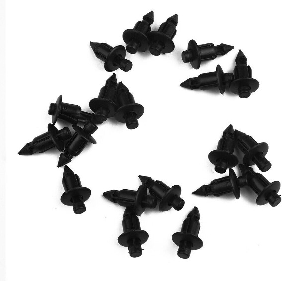
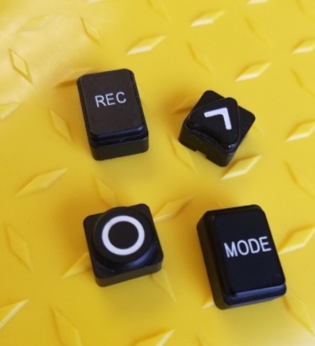
MIM is also used to make components like SIM card trays, camera rings, and buttons. These components require high - precision manufacturing to fit seamlessly into the sleek designs of modern consumer electronics. With the continuous development of the consumer electronics industry towards smaller, thinner, and more multifunctional products, the demand for MIM - produced components is expected to grow. For instance, as the number of cameras on smartphones increases and the demand for high - quality camera modules rises, the need for precise MIM - made camera rings and related components will also increase. According to market research, the market for MIM components in consumer electronics is projected to grow at a compound annual growth rate of over 10% in the next five years.
4. Automotive
In the automotive industry, MIM is applied to the production of various components. One of the key applications is in the manufacturing of turbocharger components. Turbochargers play a crucial role in improving the performance and fuel efficiency of engines. MIM - produced turbocharger components, such as turbine wheels and compressor wheels, can have complex shapes and high - precision tolerances. These components need to withstand high temperatures, high rotational speeds, and significant mechanical stresses. MIM - made turbine wheels can be designed to have optimized aerodynamic shapes, which improve the efficiency of the turbocharger. Research indicates that MIM - produced turbine wheels can increase the efficiency of the turbocharger by up to 10%, leading to better engine performance and reduced fuel consumption.
MIM is also used for the production of rotating and vibrating parts in internal combustion engines and gas turbines. These parts require high - strength materials and precise manufacturing to ensure smooth operation and long - term reliability. MIM allows for the production of parts with complex geometries that can reduce the weight of the components while maintaining their mechanical strength. For example, MIM - made connecting rods in engines can be designed to have a more optimized cross - sectional shape, reducing their weight by up to 20% compared to traditional forged connecting rods, which in turn improves the fuel efficiency and performance of the engine.
Yigu Technology's View
As a non - standard plastic metal products custom Supplier, Yigu Technology highly values the potential of Metal Injection Molding (MIM) technology. We recognize the numerous advantages it offers, such as the ability to create complex - shaped components with high precision and near - net - shape accuracy.
In our actual production, we often utilize MIM technology to meet the demands of clients for complex - shaped metal parts. For example, when manufacturing components for high - end consumer electronics, the complex internal structures and high - precision requirements can be effectively achieved through MIM. By leveraging this technology, we can not only enhance the product quality but also improve production efficiency. The high - volume production capabilities of MIM allow us to meet large - scale orders in a timely manner. We are committed to further exploring and applying MIM technology to provide our clients with more innovative and high - quality non - standard plastic metal products.
FAQs
1. What types of metals can be used in Metal Injection Molding?
A wide range of metals can be used in MIM. Stainless steels are commonly used due to their corrosion resistance, making them suitable for applications in the medical, food, and marine industries. For example, 316L stainless steel is often used in medical device components. Titanium alloys are also popular, especially in the aerospace and medical fields, because of their high strength - to - weight ratio and biocompatibility. Nickel - based alloys are utilized in high - temperature applications, such as in aircraft engines, as they can maintain their mechanical properties at elevated temperatures. Other materials like tungsten alloys, which have high density and are used in applications requiring high mass or radiation shielding, can also be processed through MIM.
2. How accurate are the parts produced by Metal Injection Molding?
Parts produced by MIM can achieve high accuracy. Generally, the dimensional tolerance of MIM - produced parts can reach ±0.1% - ±0.5% of the nominal dimension. For instance, in the production of components for the electronics industry, such as SIM card trays, the high precision of MIM allows for tight tolerances. This level of accuracy is crucial in applications where components need to fit precisely together, like in miniature mechanical assemblies or high - precision optical devices. The high - precision nature of MIM parts reduces the need for extensive post - processing to achieve the required fit and function.
3. What are the common defects in Metal Injection Molding and how to avoid them?
Common defects in MIM include black lines, pores, and deformation. Black lines are often caused by the degradation of the binder or the presence of impurities in the feedstock. To avoid this, strict control of the injection speed and pressure is necessary. For example, a proper injection speed can prevent overheating of the feedstock, which could lead to binder degradation. Pores are usually due to air entrapment during injection or incomplete sintering. To address this, optimizing the injection process to ensure proper venting of the mold can prevent air from being trapped. During sintering, controlling the heating rate and atmosphere can help achieve complete densification and reduce porosity. Deformation may occur during debinding or sintering due to uneven stress distribution. Precise control of the debinding and sintering parameters, such as a slow and uniform heating rate, can minimize deformation. Additionally, proper design of the part and the mold can also help prevent deformation by ensuring uniform material flow and stress distribution.