Introduction
Injection moulding seems simple: melt plastic, inject it into a mould, let it cool, and pop out a part. But behind that simple idea lies a world of precise mathematics. Injection mould design calculations determine whether your parts come out perfect—or come out as scrap.
Getting these calculations right affects everything. Material costs, cycle times, part quality, and tool life all depend on accurate numbers. Skip the math, and you risk warped parts, incomplete fills, or moulds that simply don’t work.
This guide breaks down the essential calculations you need to know. We’ll cover material requirements, mould dimensions, flow and pressure, and cooling systems. No advanced degrees required—just practical math that makes your projects succeed.
Why Do These Calculations Matter So Much?
Cost Control Starts with Numbers
Every gram of plastic costs money. Every second of cycle time adds up. Accurate calculations help you predict exactly what you’ll need.
Consider a production run of 500,000 parts. If your material estimate is off by just 2 grams per part, that’s 1,000 extra kilograms of plastic. At $2 per kilogram, that’s $2,000 in unnecessary cost. Over multiple projects, those small errors become huge expenses.
Quality Depends on Precision
The difference between a good part and a reject often comes down to fractions of a millimeter. Shrinkage calculations ensure your final dimensions match the design. Pressure calculations prevent short shots where the mould doesn’t fill completely. Cooling calculations stop warpage before it starts.
In medical device manufacturing, a 0.05 mm deviation can make a component unusable. That’s thinner than a human hair. Calculations at the design stage prevent these failures.
Efficiency Drives Profitability
Faster cycles mean more parts per hour. Lower defect rates mean less waste. Optimized calculations help you find the sweet spot between speed and quality.
A factory we worked with reduced their cycle time by 18% by recalculating their cooling channels. That added 3,000 extra parts per shift without new equipment.
What Material-Specific Calculations Do You Need?
How Do Shrinkage Rates Affect Dimensions?
Plastics shrink as they cool. Different materials shrink by different amounts. If you don’t account for this, your parts will come out smaller than intended.
| Material | Typical Shrinkage Rate | Application Example |
|---|---|---|
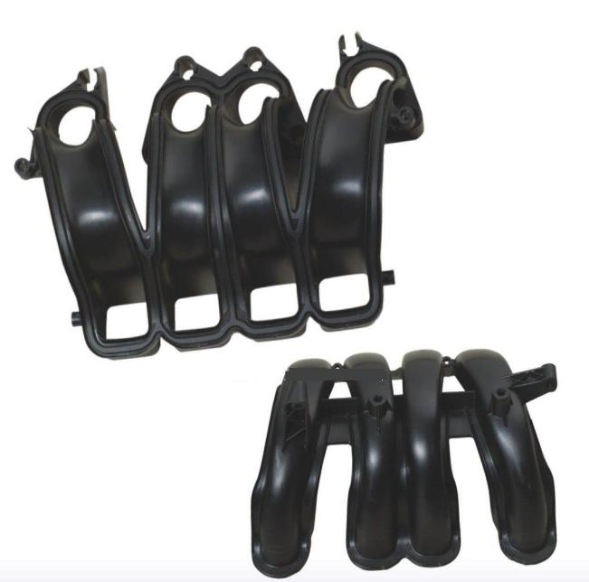
| PP | 1.5% – 3.0% | Containers, automotive parts |
| PE | 1.5% – 3.0% | Bottles, packaging |
| ABS | 0.4% – 0.9% | Electronics housings, toys |
| PC | 0.5% – 0.8% | Lenses, safety equipment |
Here’s how the calculation works. If you need a finished part length of 100 mm using ABS with 0.6% shrinkage, your mould cavity must be larger.
Formula:
- Cavity dimension = Final dimension × (1 + Shrinkage rate)
- 100 mm × (1 + 0.006) = 100.6 mm
A consumer electronics company once skipped this step. Their smartphone cases came out 0.8 mm too short. Components wouldn’t fit. The entire production batch was scrap—over $30,000 in losses.
How Do You Calculate Material Requirements?
Knowing how much plastic you need prevents waste and ensures consistent production.
First, calculate the part volume. For simple shapes, use basic geometry. For complex parts, 3D modelling software gives accurate numbers.
Then add the runner and gate volume. These channels carry plastic to the cavity. They consume material with every shot.
Example:
- Part volume: 50 cm³
- Runner and gate volume: 15 cm³
- Total volume per shot: 65 cm³
- Material density (ABS): 1.05 g/cm³
- Mass per shot: 65 × 1.05 = 68.25 grams
Multiply by the number of cavities. For a 4-cavity mould, each shot uses 273 grams of material.
What Mould Structure Calculations Are Critical?
How Do You Set Cavity and Core Dimensions?
The cavity forms the outside of your part. The core forms the inside. Their dimensions must account for both shrinkage and tolerance requirements.
For high-precision parts, tolerances can be as tight as ±0.01 mm. Optical lenses and medical components fall into this category.
Calculation approach:
- Nominal part dimension: 50.00 mm
- Shrinkage rate: 0.6%
- Cavity dimension: 50.00 × (1.006) = 50.30 mm
- Add tolerance: 50.30 ± 0.02 mm
The mould maker then machines the cavity to these expanded dimensions. After cooling and shrinkage, the final part lands right at 50.00 mm.
How Thick Should Mould Plates Be?
Mould plates face enormous pressure during injection. Too thin, and they flex. Flexing leads to uneven wall thickness, flash (excess material), or even mould damage.
The calculation considers:
- Injection pressure force (F): Typically 500–2,000 tons for industrial moulds
- Plate width (b): Unsupported span
- Material strength: Steel modulus (E) is about 200,000 MPa
A simplified formula for plate thickness:
- t = √(3 × F × b² ÷ (E × allowable stress))
A client once built a mould with plates 30% thinner than recommended. On the first production run, the plates bowed under pressure. Parts had visible thickness variations. Remaking the plates cost $8,000 and delayed the project by three weeks.
What Flow and Pressure Calculations Matter?
How Do You Predict Plastic Flow?
Molten plastic doesn’t just fill a cavity—it flows in complex patterns. Flow analysis predicts how it moves, where it might trap air, and whether it fills completely.
The key factors:
- Melt temperature: Higher temps lower viscosity but risk degradation
- Injection speed: Too fast causes jetting; too slow causes short shots
- Flow path length: Longer paths need higher pressure
In a complex automotive part with long, thin ribs, flow analysis revealed a potential short shot. Adding a small flow leader—a temporary thickening of the wall—solved the problem before steel was cut.
How Do You Calculate Injection Pressure?
Injection pressure must be high enough to fill the cavity but not so high it damages the mould or causes flash.
Basic formula:
- Pressure = Force ÷ Area
But the real calculation involves pressure drop along the flow path. The Hagen-Poiseuille equation helps estimate this for simple channels:
- ΔP = (128 × μ × L × Q) ÷ (π × d⁴)
Where:
- μ = viscosity (material property)
- L = flow path length
- Q = flow rate
- d = channel diameter
Notice the diameter to the fourth power. A small change in channel size dramatically affects pressure drop. Doubling the diameter reduces pressure drop by 94%.
A manufacturer of thin-walled containers struggled with incomplete fills. Their runner diameter was 2.5 mm. Increasing it to 3.2 mm—a modest 28% increase—dropped pressure requirements by nearly 60%. The problem disappeared.
What Cooling System Calculations Optimize Production?
Why Does Cooling Efficiency Matter?
Cooling takes up most of the injection cycle. It’s often 50% to 80% of total cycle time. Faster cooling means more parts per hour.
Heat must be removed evenly. Uneven cooling creates internal stresses. Those stresses cause warpage. Warped parts are rejects.
How Do You Calculate Cooling Channel Size?
The heat transfer calculation starts with how much heat needs to move.
Heat to remove:
- Q = m × c × ΔT
Where:
- m = mass of plastic per shot
- c = specific heat capacity of the material
- ΔT = temperature drop from melt to ejection
For a 200-gram ABS part:
- Specific heat (c): 1.7 J/g°C
- Melt temperature: 230°C
- Ejection temperature: 90°C
- ΔT = 140°C
- Q = 200 × 1.7 × 140 = 47,600 Joules
This heat must be carried away by water flowing through cooling channels. Channel diameter affects flow rate and cooling efficiency.
| Channel Diameter | Typical Flow Rate | Cooling Efficiency |
|---|---|---|
| 6 mm | Low | Slow cooling |
| 8 mm | Moderate | Balanced |
| 10 mm | High | Fast cooling, limited by mould space |
How Do You Calculate Cooling Time?
Cooling time depends on wall thickness more than any other factor.
A rough rule of thumb:
- For every 1 mm of wall thickness, cooling takes 30–60 seconds
But precise calculation uses:
- t = (h² ÷ (π² × α)) × ln( (8 ÷ π²) × (T_melt – T_mould) ÷ (T_eject – T_mould) )
Where h is wall thickness and α is thermal diffusivity.
A practical example: A 2 mm wall in ABS with good cooling channels might cool in 12–15 seconds. A 4 mm wall in the same material might take 40–50 seconds. Doubling wall thickness roughly quadruples cooling time.
A toy manufacturer redesigned a product to reduce maximum wall thickness from 4 mm to 2.5 mm. Cycle time dropped from 48 seconds to 22 seconds. Annual production capacity increased by 55,000 units without new machines.
Conclusion
Injection mould design calculations aren’t just academic exercises. They’re practical tools that save money, improve quality, and boost production rates. Getting them right means:
- Parts that match your design dimensions
- Minimal material waste
- Faster cycles
- Longer mould life
- Fewer rejects
Start with accurate material data. Understand your part geometry. Run flow and cooling simulations when possible. And always verify calculations with real-world trials.
The math might seem detailed. But each calculation answers a specific question that affects your bottom line. Master these, and you master injection moulding.
FAQ
What’s the most common mistake in injection mould design calculations?
Using incorrect shrinkage rates. Many designers rely on generic values instead of material-specific data from their actual supplier. Shrinkage varies by material grade, processing conditions, and even part geometry. Always verify with the specific resin you’ll use.
How accurate do calculations need to be?
It depends on your application. For general consumer products, ±0.1 mm may be fine. For precision components like gears or medical devices, you need ±0.01 mm or better. The tighter the tolerance, the more critical accurate calculations become.
Can simulation software replace manual calculations?
Simulation tools (like Moldflow or Moldex3D) are powerful, but they don’t replace understanding. They give results—you still need to interpret them. Use software to validate and refine your manual calculations, not to skip them entirely.
How do I account for multiple cavities in calculations?
Multiply your per-cavity material volume by the number of cavities. But remember that runner systems become more complex. The flow path length changes, and pressure drop calculations must account for how plastic splits to fill each cavity evenly.
What’s the best way to estimate cooling time for a new part?
Start with wall thickness. For a rough estimate, use 30–60 seconds per millimeter of wall thickness. For precision, run a thermal analysis. The most accurate method is to test with a prototype mould and measure actual cooling curves.
Contact Yigu Technology for Custom Manufacturing
At Yigu Technology, we apply these calculations every day. Our engineers combine practical experience with advanced simulation tools to design moulds that perform. Whether you need a simple prototype tool or a high-volume production mould, we ensure accuracy from first calculation to final part.
[Contact Yigu Technology today] to discuss your project. Let’s get your numbers right from the start.