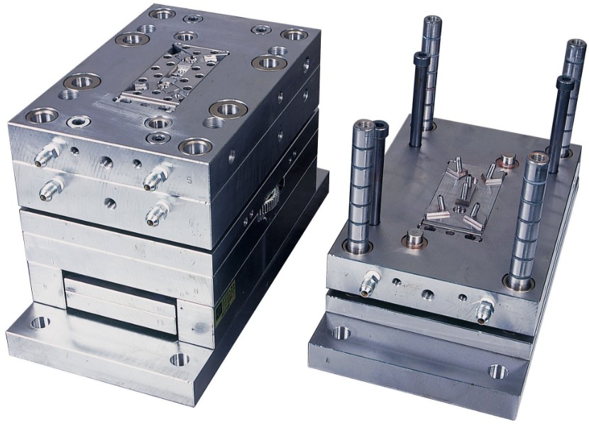
Understanding the Basics of Injection Mold Dimensions
Injection mold dimensions play a pivotal role in the production of plastic parts. Precise dimensions are crucial as they directly impact the functionality, appearance, and fit of the final plastic products. Any deviation in the mold dimensions can lead to defective parts, increased production costs, and potential issues in the assembly process.
Factors Affecting Injection Mold Dimensions
Material - The Foundation of Dimension Control
The choice of plastic material is fundamental in determining injection mold dimensions. Different plastics have distinct properties that directly impact the molding process and the final dimensions of the part. For example, the thermal expansion coefficient of a material is crucial. Materials with a high thermal expansion coefficient will expand more when heated during the injection molding process and contract more upon cooling.
Take Polycarbonate (PC) and Polyethylene (PE) as an example. PC has a relatively low thermal expansion coefficient in the range of 6.5 - 7.8×10⁻⁵/°C, while for low - density PE, it can be in the range of 16 - 18×10⁻⁵/°C. This means that for a part made of PE, more allowance needs to be made for dimensional changes during the heating and cooling cycle compared to a PC part.
Another important property is the material's viscosity. High - viscosity materials, like some grades of engineering plastics, require more force to flow into the mold cavities. This can influence the design of the mold's gating and runner systems. If the viscosity is too high and the gate size is too small, the plastic may not fill the cavity completely, leading to defective parts.
Shrinkage - A Crucial Consideration
Shrinkage is one of the most significant factors in injection mold dimension design. When the molten plastic cools and solidifies in the mold, it contracts, causing a reduction in the size of the final part. The shrinkage rate is affected by multiple factors.
As mentioned before, different plastics have different shrinkage rate ranges. Here is a more detailed table showing the shrinkage rates of some common plastics:
| Plastic Material | Shrinkage Rate Range (%) |
| ABS (Acrylonitrile Butadiene Styrene) | 0.4 - 0.8 |
| PP (Polypropylene) | 1.0 - 2.5 |
| HDPE (High - Density Polyethylene) | 1.5 - 3.0 |
| PC (Polycarbonate) | 0.5 - 0.7 |
| POM (Polyoxymethylene) | 1.2 - 3.0 |
The part's geometry also plays a role. Thick - walled sections generally have a higher shrinkage rate than thin - walled sections. This is because thick - walled areas take longer to cool, allowing more time for the plastic to contract. Additionally, the presence of features such as ribs, bosses, and holes can affect the shrinkage pattern. These features can act as barriers to the uniform contraction of the plastic, leading to local variations in shrinkage.
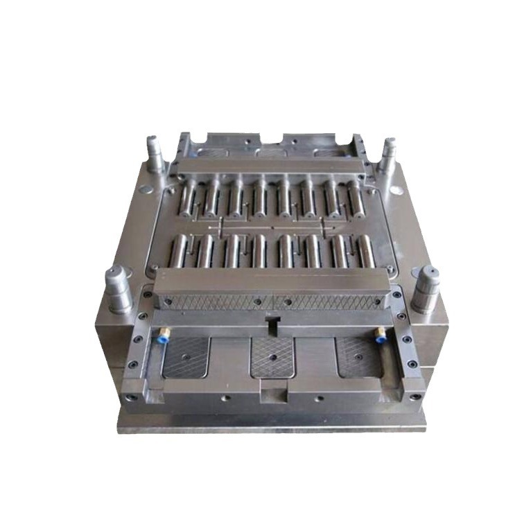
Mold Design Elements
- Gate Design: The gate is the connection between the runner system and the mold cavity. The size, shape, and location of the gate have a significant impact on the mold dimensions and the quality of the plastic part. A small gate can cause high shear stress on the molten plastic as it enters the cavity. This can lead to a higher pressure drop and potentially cause the plastic to cool prematurely, resulting in a short - shot or a part with inconsistent dimensions. For example, in a small - scale injection molding project for making small plastic toys, if the gate size was initially too small, the arms of the toys were not fully formed due to insufficient plastic flow. After increasing the gate size, the problem was resolved.
- Runner System: The runner system distributes the molten plastic from the injection nozzle to the gates of each cavity. The diameter and length of the runners can affect the pressure drop and the temperature of the plastic as it travels. Larger diameter runners can reduce the pressure drop, ensuring that the plastic reaches all cavities evenly. However, overly large runners can also lead to excessive material waste. In a multi - cavity mold for manufacturing plastic containers, an optimized runner system was designed with a specific diameter based on the flow requirements of the plastic material. This not only ensured uniform filling of all cavities but also minimized material usage.
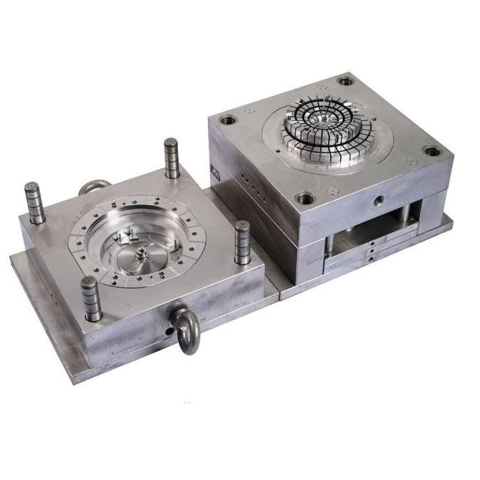
- Cooling System: An efficient cooling system is essential for controlling the shrinkage and dimensional accuracy of the plastic part. Uneven cooling can cause differential shrinkage, resulting in warping and distortion of the part. For instance, in the production of large - scale plastic panels, if the cooling channels in the mold are not evenly distributed, the panel may warp during the cooling process, making it unusable. By carefully designing the cooling channels to ensure uniform heat dissipation, the warping issue can be minimized, and the final dimensions of the panel can be maintained within the required tolerances.
Steps to Design Injection Mold Dimensions
Product Analysis
Before starting the design of injection mold dimensions, a comprehensive analysis of the target plastic part is essential.
- Function Analysis: First, understand the function of the plastic part. For example, if it's a component in a mechanical device, its dimensions need to be precise to ensure proper assembly and operation within the device. A gear in a transmission system must have accurate tooth profiles and diameters to mesh correctly with other gears.
- Shape Complexity: Evaluate the shape complexity of the part. Complex shapes with undercuts, thin - walled sections, or intricate geometries pose more challenges in mold design. A plastic part with internal threads or deep cavities requires additional considerations for mold ejection systems and proper material flow during injection.
- Size Tolerance Requirements: Determine the size tolerance requirements. Some industries, such as aerospace and medical, demand extremely tight tolerances. For aerospace components, the tolerance may be within ±0.05mm, while for general consumer products, a tolerance of ±0.2mm might be acceptable. By understanding these requirements, the mold design can be tailored to meet the specific needs of the plastic part.
Initial Dimension Calculation
Based on the product analysis, the next step is to perform the initial dimension calculation for the mold.
- Incorporating Shrinkage Rate: As mentioned earlier, the shrinkage rate of the plastic material is a crucial factor. For example, if we are designing a mold for a polypropylene (PP) part with a measured shrinkage rate of 1.5% and the desired final part size in a particular dimension is 50mm. Using the formula \(D = M(1 + S)\) (where \(D\) is the mold size, \(M\) is the 塑件 size, and \(S\) is the shrinkage rate), we can calculate the mold size in that dimension. Substituting the values, \(D=50\times(1 + 0.015)=50.75mm\). This calculation gives us the basic starting point for the mold dimension in that particular direction.
- Considering Other Factors: Other factors like the part's draft angles also need to be considered during this calculation. Draft angles are added to the mold to facilitate the easy ejection of the plastic part. If a part has a draft angle of 1°, it will affect the size of the mold cavity in the direction perpendicular to the draft. For a part with a height of 30mm and a 1° draft angle on one side, the change in dimension at the top and bottom of the part due to the draft needs to be accounted for in the mold design.
Incorporating Tolerances
Setting appropriate tolerances in the mold design is crucial for the production of high - quality plastic parts.
- Consequences of Incorrect Tolerances: If the tolerance is set too small, it can increase the manufacturing cost of the mold. Tighter tolerances require more precise machining processes, which often involve more expensive equipment and highly skilled labor. Moreover, it may lead to a higher rejection rate of the plastic parts during production as even minor variations in the molding process can cause the parts to fall out of the tight tolerance range. On the other hand, if the tolerance is set too large, the plastic parts may not fit properly with other components. For example, in an electronic device, if the tolerance of a plastic housing is too large, it may not provide a secure fit for the internal circuit boards, leading to issues like loose connections or poor protection against environmental factors.
- Industry Standards and Experience Data: In the injection molding industry, there are general guidelines for tolerance setting. For non - critical dimensions in consumer products, a tolerance of ±0.1 - ±0.3mm is often acceptable. For more critical applications, such as automotive engine components, the tolerance can be as tight as ±0.05 - ±0.1mm. According to industry experience, when dealing with materials that have a high shrinkage rate variation, it's advisable to set a slightly wider tolerance to account for the potential differences in shrinkage during production.
Final Design Adjustment
After the initial design is completed, it's necessary to make final adjustments to the mold dimensions.
- Based on Simulation Analysis: One of the key methods is to use simulation analysis, such as mold flow analysis. Mold flow analysis software can predict how the molten plastic will flow through the mold cavity, where potential weld lines, air traps, or areas of uneven filling may occur. If the analysis shows that there are areas with slow plastic flow, the mold dimensions may need to be adjusted. For example, the runner diameter can be increased in that area to improve the flow rate.
- Based on Trial Molding Results: Another important source of information for adjustment is the trial molding process. During trial molding, the first few plastic parts are produced using the initial mold design. These parts are then carefully inspected for any defects or dimensional inaccuracies. If the parts are found to be warped, the mold cooling system may need to be redesigned, and the mold dimensions may also need to be adjusted to compensate for the warping. By making these final adjustments, the mold can be optimized to produce high - quality plastic parts consistently.
Yigu Technology's Perspective
As a non - standard plastic metal products custom supplier, Yigu Technology understands the significance of precise injection mold dimensions. With years of experience in the industry, we know that every detail in mold dimension design matters. Our team of experts uses advanced CAD/CAM technology and in - depth material knowledge to ensure that the mold dimensions are as accurate as possible. We believe that a well - designed mold with proper dimensions not only improves the quality of plastic parts but also reduces production costs in the long run. By collaborating closely with clients, we can better understand their specific requirements and tailor the mold dimension design accordingly, ensuring that the final products meet and exceed expectations.
FAQs
Q1: How do I choose the right material for my injection - molded parts to ensure accurate dimensions?
When choosing a material for injection - molded parts to ensure accurate dimensions, first, consider the part's performance requirements. If it needs high heat resistance, materials like Polycarbonate (PC) or Polyphenylene Sulfide (PPS) might be suitable. For parts requiring good chemical resistance, materials such as Polyethylene (PE) or Polypropylene (PP) could be considered. Then, look at the shrinkage rate of the material. Materials with lower and more stable shrinkage rates, like ABS with a shrinkage rate of 0.4% - 0.8%, are easier to control dimensions during the molding process. Also, take into account the material's viscosity. High - viscosity materials may require more complex mold designs to ensure proper filling, which can affect the final dimensions.
Q2: What is the typical tolerance range for injection - molded plastic parts?
The typical tolerance range for injection - molded plastic parts varies depending on several factors. For non - critical consumer products, the tolerance can be in the range of ±0.1 - ±0.3mm. In more demanding applications such as automotive or aerospace, the tolerance can be as tight as ±0.05 - ±0.1mm. Tighter tolerances require more precise mold manufacturing and stricter control of the injection molding process, which increases the cost of both the mold and the production. Looser tolerances, on the other hand, are more cost - effective but may not be suitable for parts that need to fit precisely with other components.
Q3: Can I modify the injection mold dimensions after production starts?
Modifying injection mold dimensions after production starts is possible but extremely difficult and costly. The mold is typically made of hardened steel, and any modification requires advanced machining techniques. If the change is minor, it might be achievable through processes like EDM (Electrical Discharge Machining) or precision grinding, but this still involves significant time and expense. For major dimension changes, it may be more practical to design and build a new mold. Additionally, modifying the mold during production can disrupt the production schedule, leading to delays and potential losses in productivity.