Introduction
A well-written CNC program separates a part that runs smoothly from one that causes crashes, scrap parts, and wasted hours. CNC programming for turning is the language that tells a lathe how to shape raw material into precision components. Whether you are a machinist aiming to sharpen your skills or an engineer seeking to optimize production, understanding the logic behind the code matters more than memorizing G-code lists. This guide explores the critical concepts—coordinate systems, toolpath strategies, and cutting parameters—that turn a functional program into an exceptional one. We will focus on the why behind each decision, helping you write code that runs reliably, produces accurate parts, and maximizes machine efficiency.
What Defines CNC Programming for Turning?
CNC programming for turning is the process of creating a set of instructions that controls a CNC lathe or turning center. Unlike milling, where the tool spins and the workpiece stays fixed, turning involves a rotating workpiece while a stationary cutting tool removes material. The result is cylindrical, conical, or faced features.
The programmer’s job is to translate a part blueprint into a logical sequence of machine movements. This involves:
- Selecting appropriate cutting tools
- Defining efficient toolpaths
- Calculating spindle speeds and feed rates
- Applying compensations for tool geometry and wear
A deep understanding of machine capabilities, material behavior, and cutting physics defines expert-level programming. For example, programming a hydraulic piston rod requires not just contouring skills but also knowledge of heat dissipation to prevent thermal distortion during deep cuts.
Which Coordinate System Suits a Turning Center?
Understanding the X and Z Axes
Turning centers use a two-axis coordinate system: X and Z.
- Z-axis: Parallel to the spindle axis. Positive Z moves the tool away from the spindle face.
- X-axis: Radial direction. Positive X moves the tool away from the spindle centerline.
This differs from milling, where the Z-axis is vertical. A key distinction is diameter programming versus radius programming. Most modern CNC turning controls use diameter programming for the X-axis. This means an X command of U10.0 moves the tool to a 10 mm diameter—not a 10 mm radius. This system aligns directly with part print dimensions, reducing calculation errors.
Setting the Work Coordinate System
Programmers must also understand the machine reference point and work coordinate system (WCS). The WCS establishes the program’s zero point relative to the part. Common methods include using G50 or G54–G59 codes. Setting this correctly ensures that all subsequent moves reference a consistent origin.
How Do G-Codes Differ for OD vs ID Cuts?
While fundamental G-codes like G00 (rapid traverse) and G01 (linear interpolation) remain the same, the strategy for outer diameter (OD) and inner diameter (ID) cuts differs significantly.
| Aspect | OD Turning | ID Turning (Boring) |
|---|---|---|
| Primary contouring codes | G71 (roughing) / G70 (finishing) | G71 / G70, but tool clearance is critical |
| Tool geometry | Turning tools with positive rake | Boring bars—longer, prone to deflection |
| Chip evacuation | Chips fall away naturally | Challenging; often requires peck cycles (G74) |
| Surface speed | Constant for a given diameter | RPM must increase as bore diameter decreases |
| Tool nose radius compensation | G42 for facing toward chuck | G41 for boring toward chuck |
Practical example: When roughing an OD with G71, the tool can safely move in two axes simultaneously. For a deep, small-diameter ID, a peck boring cycle (G74) is often essential. This breaks chips and prevents jamming—a step rarely needed for OD work.
Where Does Tool-Nose Radius Compensation Fit?
Why a Rounded Tool Tip Matters
Every turning insert has a finite nose radius—not a perfectly sharp point. Without tool-nose radius compensation (TNRC), the toolpath follows the center of this radius. This leads to dimensional errors, especially on tapers and arcs.
How TNRC works:
TNRC, activated by G41 (left compensation) or G42 (right compensation), instructs the control to offset the toolpath by the radius value. This ensures the cutting edge contacts the programmed contour.
Tool Orientation Codes
The tool geometry orientation—a code from 1 to 9 in the tool offset registry—tells the control where the tool’s imaginary “tip” sits relative to the part. For example, a standard OD turning tool is often set as orientation 3.
Common mistake: Programming a sharp corner. A rounded insert cannot cut a true sharp inside corner unless a chamfer or radius is programmed. The tool will leave an undercut, potentially compromising part strength or assembly fit.
When to Switch from Roughing to Finishing?
The transition from roughing to finishing is a balance between speed and quality. A well-timed switch ensures final dimensions and surface finish meet specifications.
Indicators for the Switch
- Stock remaining: Approximately 0.5 mm to 1.5 mm on the diameter, depending on material stability and required finish.
- Thermal stability: Roughing generates heat. Allowing a final pass with a sharp insert and consistent cut depth ensures heat doesn’t distort tolerances.
- Tool change: Using a dedicated finishing insert with a specific nose radius and coating yields better results.
Multiple Finishing Passes
For ultra-tight tolerances, professionals often use multiple finishing passes. The first pass removes the bulk of the finish allowance. A second pass—with the same offset—removes material that sprung back due to residual stresses.
Example: For a 4140 steel shaft requiring a 0.8 µm Ra finish, you might:
- Rough with a 0.4 mm radius insert
- Leave 0.25 mm per side
- Finish with a sharp 0.8 mm radius wiper insert at constant surface speed
Why Set a Precise Spindle Speed Limit?
Setting a spindle speed limit is not optional—it is a safety and quality requirement.
Safety Considerations
A G50 or G92 code sets the maximum spindle speed. This prevents:
- The spindle from exceeding safe rotational speeds for large-diameter chucks
- Catastrophic failure from unbalanced workpieces
A 300 mm diameter steel chuck has a much lower maximum safe RPM than a 50 mm chuck. Without a limit, the machine could attempt speeds beyond its mechanical limits.
Constant Surface Speed Control
When using constant surface speed (CSS) mode (G96), the control automatically increases RPM as the tool moves toward the center on a face cut. Without a limit (e.g., G50 S2500), the spindle could theoretically approach infinite RPM at the centerline—a dangerous scenario.
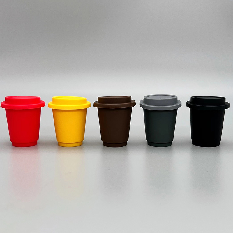
Material Integrity
Certain materials, such as plastics or thin-walled tubing, can deform or melt if spindle speeds run too high. Excessive friction generates heat that compromises material properties.
How Is Feed Rate Optimized Per Material?
Feed rate optimization directly impacts productivity and tool life. It forms a triad with spindle speed and depth of cut.
General Rules
- Harder materials: Lower feed rates
- Softer, gummier materials: Higher feeds to achieve proper chip formation
Chip Load Guidelines
Insert manufacturer recommendations provide a starting point. Below are typical ranges:
| Material | Roughing Feed (mm/rev) | Finishing Feed (mm/rev) |
|---|---|---|
| Aluminum 6061 | 0.25–0.4 | 0.05–0.15 |
| AISI 1045 Steel | 0.2–0.3 | 0.05–0.1 |
| Inconel 718 | 0.1–0.15 | 0.03–0.08 |
Chip Monitoring
Experienced programmers monitor chip color and shape to fine-tune feeds.
- In steel: A blue chip indicates optimal heat carry-away.
- Dark purple or black chip: Feed may be too low, causing heat to build up in the part.
- Long, stringy chip: Feed rate may be too low for the depth of cut. Chip breaking becomes critical for reliable operation.
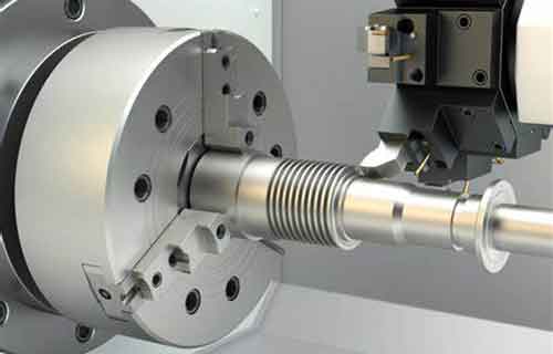
A Real-World Case: Hydraulic Piston Rod
A manufacturer producing hydraulic piston rods faced inconsistent surface finish and premature tool wear. The existing program used a single roughing cycle followed by one finishing pass, with no spindle speed limit and generic feed rates.
After analysis, the programming team implemented:
- G50 S2200 to cap spindle speed during CSS operations
- G71 roughing cycle leaving 0.4 mm per side
- Two finishing passes: first at 0.25 mm depth, second at 0.15 mm with a wiper insert
- Feed rates adjusted per material batch (1045 steel: 0.22 mm/rev roughing, 0.08 mm/rev finishing)
Results:
- Surface finish improved from Ra 1.6 µm to Ra 0.7 µm
- Tool life increased by 40%
- Scrap rate dropped from 5% to under 1%
- Cycle time decreased by 18% due to optimized roughing parameters
Conclusion
Mastering CNC programming for turning goes beyond memorizing G-codes. It requires understanding the coordinate system, applying appropriate strategies for OD and ID work, leveraging tool-nose radius compensation, timing the rough-to-finish transition wisely, setting prudent spindle limits, and optimizing feeds based on material behavior. The most effective programmers visualize the cutting process as they write each line of code. They anticipate how heat, deflection, and chip formation will affect the final part. This mindset transforms a program from a simple set of instructions into a reliable recipe for consistent, high-quality production.
FAQs
What is the most common mistake beginners make in CNC turning programming?
Forgetting to account for tool-nose radius compensation, which causes inaccurate tapers and arcs. Another frequent error is failing to set a spindle speed limit (G50) when using constant surface speed (G96)—a significant safety hazard.
How do I choose between G71 and G73 roughing cycles?
Use G71 (longitudinal roughing) for material removal on straight or contoured OD/ID profiles where the stock is a solid bar or tube. Use G73 (pattern repeating) for workpieces with pre-formed stock, such as castings or forgings, where material is already close to final shape. G73 follows a repeating pattern with even chip loads.
Can I use the same feed rate for roughing and finishing?
Almost never. Roughing feeds prioritize metal removal rate and are typically higher. Finishing feeds are lower and often paired with higher spindle speeds to achieve the desired surface finish (Ra value). Using roughing feeds for finishing results in poor surface quality.
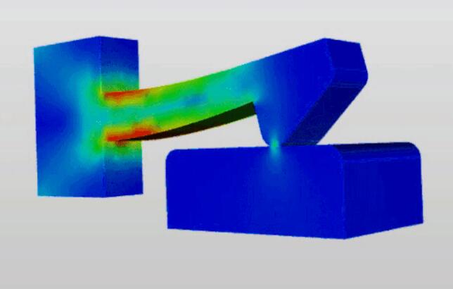
Why does my finish pass leave material that roughing should have removed?
This is usually due to tool deflection during roughing or thermal expansion of the part. The material “springs back” after the roughing tool passes. Adding a spring pass—a second finishing pass with the same coordinates and offset—typically resolves the issue.
What does “constant surface speed” (G96) mean, and why is it important?
Constant surface speed automatically adjusts spindle RPM to maintain a consistent cutting speed (in meters per minute) at the tool-workpiece contact point. This is critical for consistent chip formation, tool life, and surface finish across different diameters on a single part.
Contact Yigu Technology for Custom Manufacturing
At Yigu Technology, we view CNC programming for turning as the invisible engine that drives part quality and manufacturing efficiency. Our engineering team combines deep programming expertise with hands-on machining experience to develop optimized turning programs. We prioritize tool life, cycle time reduction, and dimensional integrity—especially for complex, high-precision, or high-volume components.
We use advanced CAM simulation and in-house machining trials to validate every program before production begins. This ensures your custom manufacturing project runs flawlessly from the first piece. If you are seeking a manufacturing partner that treats CNC programming as a strategic asset, contact Yigu to discuss your turning project today. Let us turn your designs into precisely executed reality.