Understanding the Basics of 3D Printing Process Diagram
A 3D printing process diagram is a visual representation that details the step - by - step procedures involved in creating a three - dimensional object using additive manufacturing technology. It is an essential tool for both beginners and professionals in the 3D printing field.
Importance in Comprehending 3D Printing
- Clarity of the Process: The diagram breaks down the complex 3D printing process into understandable stages. For instance, it shows how a digital 3D model is first created using CAD (Computer - Aided Design) software or obtained from a 3D scanner. This model is then sliced into thin layers by slicing software. Each layer's data is sent to the 3D printer, which deposits material layer by layer to build the final object. According to a study by the Wohlers Report, about 80% of new users in 3D printing found that understanding the process diagram significantly reduced the learning curve when starting with 3D printing.
- Troubleshooting: In case of any issues during the 3D printing process, such as layer adhesion problems or incorrect dimensional accuracy, the process diagram can be used to identify where things might have gone wrong. For example, if the model has gaps between layers, it could be related to the extrusion rate in the material - deposition stage shown in the diagram.
Applications in Different Industries
- Medical Field: In medical applications, 3D printing process diagrams are crucial for creating custom - made prosthetics, implants, and anatomical models. Surgeons can use these diagrams to understand how a patient - specific implant will be fabricated. For example, a 3D - printed cranial implant is designed based on a patient's CT scan data. The process diagram shows how the scan data is converted into a 3D model, then sliced, and finally printed using biocompatible materials like titanium alloys.
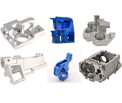
- Aerospace Industry: Aerospace companies use 3D printing to produce lightweight and complex parts. The process diagram helps in ensuring the quality and precision of these parts. For instance, when printing a turbine blade, the diagram details how the metal powder (such as nickel - based superalloys) is melted and fused layer by layer using selective laser melting (SLM), a type of 3D printing technology. This ensures that the final part meets the high - strength and heat - resistance requirements of aerospace applications.
- Automotive Industry: In automotive manufacturing, 3D printing is used for rapid prototyping and producing low - volume parts. The process diagram enables designers and engineers to visualize the production of parts like custom - designed engine components or interior trims. For example, a car manufacturer might use fused deposition modeling (FDM) to print a prototype of a new dashboard design. The diagram shows how the thermoplastic filament (such as ABS or PLA) is melted and extruded to build the part layer by layer.
Key Elements in a 3D Printing Process Diagram
Digital Design (CAD Model)
The 3D printing journey commences with digital design, often in the form of a CAD (Computer - Aided Design) model. This is a virtual representation of the object to be printed, created using specialized software such as AutoCAD, SolidWorks, or Blender. Designers need to pay attention to details like wall thickness, overhangs, and proper dimensioning. For example, a wall thickness that is too thin may lead to structural instability during the printing process. According to a survey by 3D Hubs, about 70% of 3D printing failures related to design are due to improper wall thickness settings.
Slicing the Model
Once the CAD model is ready, it is time to slice it. Slicing software, such as Cura or Simplify3D, divides the 3D model into thousands of thin horizontal layers. Each layer contains instructions on how the 3D printer should deposit material. Parameters like layer height, infill density, and extrusion width are crucial during this stage. A smaller layer height results in a smoother surface finish but increases the printing time. For instance, reducing the layer height from 0.2 mm to 0.1 mm can double the printing time for a medium - sized object, but it will significantly improve the surface quality.
Printing Materials
There is a wide range of materials available for 3D printing. Some of the most common ones include:
- PLA (Polylactic Acid): It is a biodegradable and easy - to - print thermoplastic. PLA has a relatively low melting point, making it suitable for beginners. It is often used for creating decorative items, prototypes, and educational models.
- ABS (Acrylonitrile Butadiene Styrene): ABS is more durable and heat - resistant than PLA. It is frequently used in applications where strength and toughness are required, such as in the automotive and electronics industries for making parts like brackets and enclosures.
- PETG (Polyethylene Terephthalate Glycol - modified): PETG combines the best features of PLA and ABS. It has good impact resistance, is heat - resistant, and has excellent layer adhesion. It is often used for functional parts and items that need to be dishwasher - safe.
- Nylon: Nylon is known for its high strength, flexibility, and abrasion resistance. It is used in applications like creating gears, bearings, and other mechanical components.
The Printing Process Itself
Let's take Fused Deposition Modeling (FDM), one of the most popular 3D printing technologies, as an example. In FDM, a spool of thermoplastic filament (such as PLA or ABS) is fed into the printer's extruder. The extruder heats the filament to its melting point and then extrudes it through a nozzle. The nozzle moves in a precise pattern, depositing the melted material layer by layer onto a build platform. As the material cools, it solidifies, bonding with the previous layer. During the printing process, factors like temperature control, nozzle movement speed, and extrusion rate need to be carefully monitored. If the extrusion rate is too high, the printed object may have bulges or uneven surfaces; if it's too low, there may be gaps between layers.
Post - Processing
After the 3D printing is complete, post - processing steps are often necessary. These steps can include:
- Removing Support Structures: Support structures are often added during the printing process to hold up overhanging parts. Once the printing is done, these supports need to be carefully removed. In some cases, they can be easily snapped off, while in others, tools like pliers or cutters may be required.
- Sanding and Finishing: Sanding can be used to smooth out rough surfaces, and additional finishing techniques such as polishing can be applied to give the object a more professional look. For example, a 3D - printed jewelry piece may be sanded and polished to make it shiny and smooth.
- Painting: Painting can add color and further enhance the appearance of the printed object. Specialized 3D - printing paints are available that adhere well to different materials. This step is crucial as it can transform a plain - looking 3D - printed object into a visually appealing and functional product.
Comparing Different 3D Printing Technologies through Diagrams
SLA (Stereolithography Apparatus)
SLA is one of the earliest 3D printing technologies. The following is a simple diagram to show its printing process:
[Here you can insert a diagram of SLA process, for example, a diagram showing a vat of liquid resin, a laser beam scanning on the surface of the resin, and the solidified resin layer by layer]
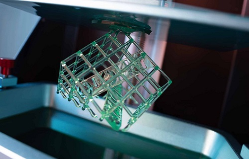
In the SLA process, a vat is filled with a photosensitive resin. A UV laser beam is projected onto the surface of the liquid resin. The laser beam traces the cross - sectional shape of the object's layer according to the sliced data. As the laser hits the resin, it cures the resin in the traced area, solidifying it into a thin layer. After one layer is completed, the build platform is lowered by a certain height (equal to the layer thickness), and a new layer of resin is coated on the previously solidified layer. Then the laser scans again to solidify the next layer. This process repeats until the entire 3D object is formed.
Advantages:
- High Precision: SLA can achieve very high precision, with layer thicknesses as small as 0.05 - 0.1 mm in some cases. This makes it ideal for creating highly detailed models, such as jewelry prototypes, dental models, and intricate figurines. For example, in jewelry design, SLA can accurately reproduce the fine details of a complex ring setting, with features like small gem - holding prongs being precisely formed.
- Smooth Surface Finish: The cured resin layers bond well together, resulting in a relatively smooth surface finish. This reduces the need for extensive post - processing in many cases, saving time and effort.
Limitations:
- Material Limitations: SLA mainly uses photosensitive resins, and the variety of available resins is more limited compared to some other 3D printing technologies. Also, the mechanical properties of the cured resin may not be as good as some engineering plastics or metals, so it may not be suitable for applications that require high - strength or heat - resistant parts.
- Cost: SLA printers and their associated materials tend to be relatively expensive. The cost of the UV laser system and the need for high - quality photosensitive resins contribute to the overall high cost, which may be a barrier for some small - scale users or budget - constrained projects.
SLS (Selective Laser Sintering)
The SLS printing process can be shown in the following diagram:
[Insert a diagram of SLS process, which may include a powder bed, a laser scanning over the powder, and the sintered powder gradually forming a 3D object]
In SLS, a powder bed is filled with powdered material, which can be plastic, metal, ceramic, or other materials. A laser beam is used to selectively heat and sinter the powder particles together according to the cross - sectional pattern of each layer. Once one layer is sintered, the powder bed is lowered by the thickness of one layer, and a new layer of powder is spread on top. The laser then sinters the next layer onto the previous one.
Advantages:
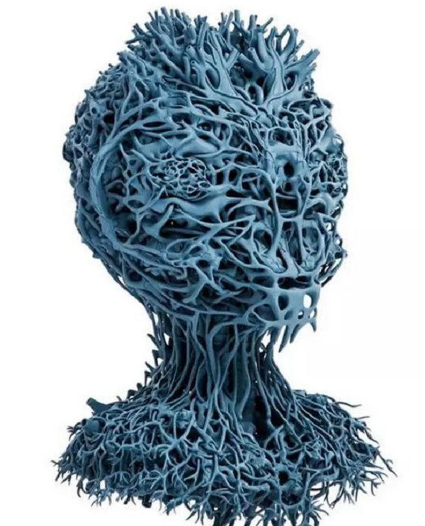
- Complex Structure and High - Performance Parts: SLS is well - suited for creating complex structures and high - performance parts. Since the powder supports the part during the printing process, there is no need for additional support structures in most cases. This allows for the creation of parts with internal cavities, overhangs, and complex geometries. For example, in aerospace applications, SLS can be used to print lightweight yet strong metal parts with complex internal lattice structures to reduce weight while maintaining structural integrity.
- Material Versatility: SLS can work with a wide range of materials, including nylon, polycarbonate, metal powders (such as titanium, aluminum), and ceramic powders. This makes it applicable to various industries, from automotive to medical.
Disadvantages:
- High Cost: Similar to SLA, SLS also has a high cost associated with it. The SLS printers are expensive, and the powdered materials can be costly, especially in the case of metal powders. Additionally, post - processing steps such as removing excess powder and heat - treating the printed part can add to the overall cost.
- Surface Finish and Dimensional Accuracy: Although SLS can produce high - quality parts, the surface finish is generally not as smooth as that of SLA - printed parts. There may be a rough texture due to the nature of the sintering process. Also, achieving extremely high dimensional accuracy can be challenging, especially for large - scale parts.
Yigu Technology's Perspective
As a non - standard plastic and metal products custom supplier, Yigu Technology highly values the 3D printing process diagram. It serves as a cornerstone in our custom manufacturing process. By carefully studying the process diagram, our design team can optimize product designs, ensuring they are not only functional but also cost - effective to produce. For example, we can identify areas where material usage can be minimized without sacrificing structural integrity.
Moreover, the 3D printing process diagram helps us in cost control. We can accurately estimate production time, material consumption, and potential post - processing costs, allowing us to provide more competitive quotes to our clients. Quality control is another area where the diagram plays a crucial role. We can monitor each stage of the 3D printing process, from the digital design to the final post - processing, to ensure that the products meet our high - quality standards. Yigu Technology firmly believes that 3D printing technology, with the guidance of the process diagram, will continue to revolutionize the custom - manufacturing industry, and we are excited to be a part of this innovative journey.