Introduction
Walk into any modern factory, and you will see them. Machines humming quietly, cutting metal, shaping plastic, carving wood. All guided by lines of code. This is professional CNC—Computer Numerical Control—at work. It has transformed manufacturing from a craft dependent on human skill into a precision discipline driven by software and data.
But owning a CNC machine does not guarantee success. Many manufacturers struggle to select the right equipment. Programming errors waste time and material. Inefficient toolpaths leave money on the table. And understanding how to apply CNC across different industries requires deep experience.
At Yigu Technology, we have worked with CNC technology for years. We have seen what separates successful implementations from costly mistakes. This guide walks you through the essential elements: the machines, the processes, the software, and the applications that make professional CNC indispensable in modern manufacturing.
What Types of CNC Machines Exist?
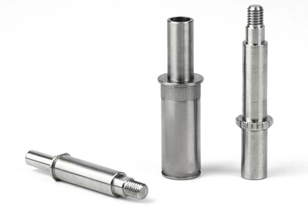
CNC Lathes
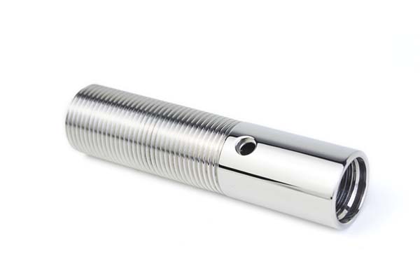
A CNC lathe is designed for turning operations. The workpiece rotates while a stationary cutting tool removes material. This creates cylindrical parts with high accuracy.
| Feature | Capability |
|---|---|
| Typical tolerance | ±0.001 mm |
| Common parts | Shafts, bolts, bushings, threaded components |
| Operations | Facing, turning, threading, boring |
Real-World Example:
A 12-inch CNC lathe can turn aluminum rods into precision-threaded bolts with consistent thread profiles. Each bolt matches the next within microns. Manual threading could not achieve this consistency.
CNC Milling Machines
A CNC milling machine uses rotating cutting tools to remove material from a stationary workpiece. It is the most versatile CNC machine type.
| Feature | 3-Axis | 5-Axis |
|---|---|---|
| Movement | X, Y, Z | X, Y, Z + two rotational axes |
| Best for | Simple parts, flat surfaces | Complex 3D shapes, undercuts |
| Setup reduction | Baseline | 40–60% fewer setups |
Real-World Example:
A 5-axis CNC milling machine can produce aerospace components with curved surfaces in a single setup. The same part would require 3–4 setups on a 3-axis machine, each introducing potential alignment errors.
CNC Routers
A CNC router is similar to a milling machine but designed for softer materials and higher speeds.
| Material | Applications | Typical Finish |
|---|---|---|
| Wood | Furniture, cabinetry, signs | Ra 1.6–6.3 μm |
| Plastics | Enclosures, prototypes | Smooth, polished |
| Composites | Aerospace tooling, panels | Requires diamond tooling |
CNC Plasma and Laser Cutters
These machines are used for cutting sheet metal. The choice depends on material thickness and precision requirements.
| Machine | Best For | Precision | Kerf Width |
|---|---|---|---|
| Laser cutter | Thin sheets (≤10 mm) | Very high | 0.1–0.3 mm |
| Plasma cutter | Thick sheets (10–50 mm) | Moderate | 1–3 mm |
Laser cutters produce clean cuts with minimal heat-affected zones. They are ideal for precision sheet metal work. Plasma cutters handle thicker materials at lower cost but with wider kerf and more heat distortion.
What Are the Key Components of a CNC Machine?
Spindle
The spindle rotates the cutting tool. Its speed range determines what materials you can machine effectively.
| Spindle Speed | Best For | Impact |
|---|---|---|
| 3,000–8,000 RPM | Heavy-duty milling, steel | High torque, stable |
| 10,000–20,000 RPM | Aluminum, plastics | Faster material removal |
| 30,000–60,000 RPM | High-speed machining, finishing | Excellent surface finish |
A 15,000 RPM spindle can reduce machining time for aluminum parts by 30–50% compared to a 5,000 RPM spindle. The higher speed allows lighter cuts at faster feeds.
Tool Holder
The tool holder secures the cutting tool. Runout—misalignment between the holder and spindle—directly affects precision.
| Tool Holder Type | Runout | Best For |
|---|---|---|
| Collet chuck | 0.005–0.01 mm | General machining |
| Hydraulic holder | 0.002–0.005 mm | High-precision work |
| Shrink-fit holder | <0.003 mm | High-speed machining |
Runout below 0.01 mm is essential for maintaining tolerance. Higher runout causes uneven tool wear and poor surface finish.
Axes and Drives
The axes (X, Y, Z) determine the machine’s work envelope. Servo motors drive each axis with precision.
| Axis | Typical Travel | Resolution |
|---|---|---|
| X (table left-right) | 500–1,000 mm | 0.0001 mm |
| Y (table in-out) | 300–600 mm | 0.0001 mm |
| Z (spindle up-down) | 300–500 mm | 0.0001 mm |
Rotary axes (A, B, C) add tilting or rotating capability. A 5-axis machine uses two rotary axes in addition to the three linear axes.
Worktable
The worktable supports the workpiece. T-slots allow clamping fixtures. Some tables include rotary axes for multi-sided machining.
What Machining Processes Does CNC Enable?
Milling
Milling removes material to create flat surfaces, slots, pockets, and contours.
| Operation | Tool | Application |
|---|---|---|
| Face milling | Face mill | Creating flat surfaces; Ra 0.8–3.2 μm on steel |
| End milling | End mill | Cutting contours, slots, pockets |
| Climb milling | Any end mill | Tool moves with rotation; reduces wear 20–30% on aluminum |
Climb milling is preferred for most CNC work. The cutting edge engages the material at the thickest point, reducing friction and heat.
Turning
Turning on a CNC lathe produces cylindrical parts.
| Operation | Description | Typical Tolerance |
|---|---|---|
| Facing | Cutting the end of the workpiece | ±0.01 mm |
| Turning | Reducing diameter along length | ±0.005 mm |
| Threading | Cutting external or internal threads | ±0.01 mm on pitch diameter |
A CNC lathe can turn a 100 mm diameter steel rod into a stepped shaft with diameter tolerances of ±0.005 mm—far tighter than manual turning.
Drilling and Cutting
Drilling creates holes. CNC machines maintain positional accuracy of ±0.02 mm for hole locations. Peck drilling cycles break chips and clear material from deep holes.
Engraving and Grinding
Engraving creates detailed patterns on metal, wood, or plastic. Resolution can be as fine as 0.01 mm per step.
Grinding on CNC grinders achieves surface finishes as smooth as Ra 0.025 μm—essential for bearing surfaces and precision molds.
How Do Precision and Efficiency Metrics Work?
Tolerance Levels
Different industries demand different levels of precision.
| Industry | Typical Tolerance | Example |
|---|---|---|
| Medical devices | ±0.001 mm | Surgical instruments, implants |
| Aerospace | ±0.002–0.005 mm | Turbine blades, structural parts |
| Automotive | ±0.01–0.02 mm | Engine components, transmission parts |
| General industrial | ±0.05–0.1 mm | Brackets, housings |
Some CNC machines can hold tolerances as low as ±0.0005 mm for critical components like aerospace sensors.
Surface Finish
Surface finish is measured by Ra (roughness average). Lower numbers indicate smoother surfaces.
| Ra Value | Appearance | Application |
|---|---|---|
| 0.025 μm | Mirror | Hydraulic cylinder bores, bearings |
| 0.4 μm | Polished | Precision molds, optical mounts |
| 0.8 μm | Smooth | Automotive engine components |
| 1.6–3.2 μm | Machined finish | General industrial parts |
Material Removal Rate (MRR)
MRR measures machining efficiency. It is the volume of material removed per minute.
Formula: MRR = Cutting Speed × Width × Depth × Feed Rate
A CNC milling machine cutting steel at 100 m/min with a 5 mm depth of cut can achieve an MRR of 500 cm³/min. Higher MRR means faster production, but tool wear and surface finish limit maximum rates.
How Is CNC Applied Across Industries?
Automotive Industry
The automotive sector is one of the largest users of CNC technology. A single CNC production line can manufacture 500 engine blocks per day, each with consistent dimensional accuracy.
Applications:
- Engine blocks and cylinder heads
- Transmission components (gears, shafts, housings)
- Suspension parts (control arms, knuckles)
- Brake components (calipers, rotors)
Aerospace Engineering
Aerospace demands the highest precision. CNC machines produce lightweight titanium components with complex geometries.
Benefits of 5-axis machining in aerospace:
- Reduces aircraft part weight by 10–15% compared to traditional methods
- Eliminates multiple setups, reducing alignment errors
- Enables complex airfoil shapes for turbine blades
Electronics Manufacturing
Electronics require precision at small scales. CNC routers cut aluminum heat sinks with intricate fins, improving heat dissipation by 20–30%.
Applications:
- Circuit board enclosures
- Connector housings
- Heat sinks
- EMI shielding components
Medical Device Production
Medical devices demand biocompatibility, precision, and consistency. CNC machining delivers.
Applications:
- Surgical instruments (scalpels, forceps)
- Orthopedic implants (hip stems, knee components)
- Dental implants and abutments
- Diagnostic equipment housings
Specialized Applications
Jewelry making uses small CNC milling machines to carve intricate designs in gold and silver. Tooling as small as 0.1 mm creates detailed patterns impossible by hand.
Woodworking with CNC routers produces custom furniture parts with perfect joints, reducing assembly time by 30–40%.
Metal fabrication shops use CNC plasma and laser cutters to shape sheet metal. CNC bending machines then form precise angles.
Prototyping is accelerated by CNC. Designers can create functional prototypes in hours instead of days, reducing product development time by 50–70%.
What Software Powers Professional CNC?
CAD and CAM Software
CAD (Computer-Aided Design) software creates 3D models of parts. Common tools include AutoCAD, SolidWorks, and Fusion 360.
CAM (Computer-Aided Manufacturing) software converts these models into toolpaths. It generates the G-code that drives the machine.
| CAM Software | Strengths |
|---|---|
| Mastercam | Industry standard; extensive post-processor library |
| Fusion 360 | Integrated CAD/CAM; cloud-based; affordable |
| NX (Siemens) | High-end; advanced 5-axis capabilities |
CAM software can simulate the machining process, detecting collisions between tool and workpiece. This reduces programming errors by 70–80% and prevents costly crashes.
Simulation Software
Simulation is essential for complex parts. A single simulation can catch errors that would otherwise ruin a $500 workpiece. It allows operators to visualize the machining process before running it on the machine.
G-Code and M-Code
G-code is the standard programming language for CNC machines. It specifies tool movements, spindle speeds, and feed rates.
| Command | Meaning |
|---|---|
| G01 X100 Y50 F200 | Linear move to X100, Y50 at 200 mm/min |
| M03 | Spindle on (clockwise) |
| M05 | Spindle off |
| M08 | Coolant on |
M-code controls auxiliary functions like coolant, spindle, and tool changes.
Toolpath Optimization
Toolpath generation in CAM software optimizes the cutting path to minimize cycle time and tool wear. A well-optimized toolpath can reduce machining time by 20–30% compared to a basic path.
Control Systems
CNC control systems (Fanuc, Siemens, Haas) interpret G-code and control the machine’s axes and spindle. Modern controls feature:
- Touchscreen interfaces
- Real-time monitoring
- Manual overrides for feed rate and spindle speed
- Diagnostic tools for troubleshooting
How Do You Choose the Right CNC Machine?
Decision Factors
| Factor | Considerations |
|---|---|
| Part size | Work envelope must accommodate largest part |
| Material | Harder materials require more rigid machines, higher torque |
| Precision | Tighter tolerances demand better spindles, scales, and thermal control |
| Complexity | 5-axis for complex geometries; 3-axis for simple parts |
| Volume | High volume may justify automation and faster machines |
| Budget | Balance upfront cost against productivity gains |
Common Mistakes
- Buying too much machine: 5-axis capability is expensive. If your parts are simple, a 3-axis machine may be sufficient.
- Buying too little machine: A machine that cannot hold required tolerances will never be useful.
- Ignoring software costs: CAM software, post-processors, and training add to the total cost.
- Underestimating training: A CNC machine is only as good as the people programming and operating it.
Yigu Technology's Perspective
At Yigu Technology, we harness professional CNC to deliver high-quality plastic and metal parts. Our shop combines advanced CNC milling and turning machines with top-tier CAD/CAM software. This allows us to meet custom requirements with tight tolerances, providing reliable solutions for automotive, electronics, and industrial clients.
We have learned that professional CNC is not just about the machine. It is about the entire ecosystem:
- Machine selection: Matching the machine to the work
- Tooling: Using the right tools for the material
- Programming: Optimizing toolpaths for efficiency
- Process control: Monitoring and adjusting in real time
- People: Skilled operators and programmers who understand the technology
When these elements come together, CNC delivers unmatched precision, consistency, and productivity.
Conclusion
Professional CNC has fundamentally changed manufacturing. It enables precision that manual methods cannot match. It produces consistent parts across thousands of units. It handles complex geometries that were impossible a generation ago.
But CNC is not a magic black box. Success requires understanding the machines, the processes, and the software that drives them. It requires selecting the right equipment for the work. And it requires skilled people who can program, operate, and optimize.
For manufacturers willing to invest in these capabilities, professional CNC is indeed a game-changer. It reduces costs, improves quality, and opens doors to new markets and applications.
FAQ
What is the difference between 3-axis and 5-axis CNC machines?
3-axis CNC machines move along X, Y, and Z axes. They are suitable for simple parts with flat surfaces. 5-axis machines add two rotational axes (A and B or C), allowing the tool to approach the workpiece from any angle. They reduce setup time by 40–60% for complex parts and improve surface finish by eliminating multiple setups and their alignment errors.
How long does it take to program a CNC machine for a custom part?
It depends on part complexity. A simple bracket can be programmed in 30–60 minutes using CAM software. Complex aerospace parts with 3D contours may take 4–8 hours, including simulation and optimization. Using templates for similar parts can reduce programming time by 30–50%. Experienced programmers and well-organized tool libraries speed the process.
Which CNC machine is best for cutting thin sheet metal?
A CNC laser cutter is ideal for thin sheet metal (up to 10 mm thick). It offers high precision with a kerf width of 0.1–0.3 mm and produces clean cuts with minimal heat-affected zones, reducing material distortion. For thicker sheets (10–50 mm), a CNC plasma cutter is more cost-effective, though with slightly lower precision and wider kerf.
What tolerance can I expect from a standard CNC machine?
Standard CNC machines typically hold tolerances of ±0.01 mm for most work. High-precision machines can achieve ±0.001 mm or better. The achievable tolerance depends on the machine's condition, tooling, material, and the operator's skill. For critical applications, verify your machine's capability through test cuts and measurement.
How do I reduce CNC machining time?
Optimize in three areas:
- Toolpaths: Use CAM software to generate efficient paths; reduce air cutting
- Cutting parameters: Increase speeds and feeds within tool limits
- Workholding: Use quick-change fixtures to reduce setup time
- Tool selection: Use the right tool for the material; coated tools often allow higher speeds
A well-optimized process can reduce cycle time by 30–50% without sacrificing quality.
Contact Yigu Technology for Custom Manufacturing
At Yigu Technology, we are professional CNC users. We combine advanced milling and turning machines with skilled programmers and operators to deliver precision components for demanding applications.
Our capabilities include 3-axis and 5-axis milling, CNC turning, and multi-process manufacturing. We work with metals, plastics, and composites across automotive, aerospace, medical, and industrial sectors.
We do not just run machines. We engineer processes. We select the right tools, optimize toolpaths, and verify dimensions with in-process inspection. The result: parts that meet specifications, delivered on time.
Contact us today to discuss your CNC manufacturing needs.