Introduction
Injection molding is the backbone of modern manufacturing. It produces the plastic parts that surround us—from the dashboard in your car to the syringe at your doctor's office. But how does a raw plastic pellet become a finished part?
The journey from concept to finished product involves seven distinct steps. Each step requires careful attention. Miss one detail, and the final part may warp, crack, or fail to meet specifications.
This guide walks you through the entire injection molding process—from material selection to post-processing. Whether you are new to manufacturing or looking to refine your process, you will find practical information to help you craft high-quality parts.
What Is Injection Molding?
Injection molding is a manufacturing process that injects molten material into a mold cavity under high pressure. The material cools and solidifies, taking the shape of the cavity. The finished part is then ejected.
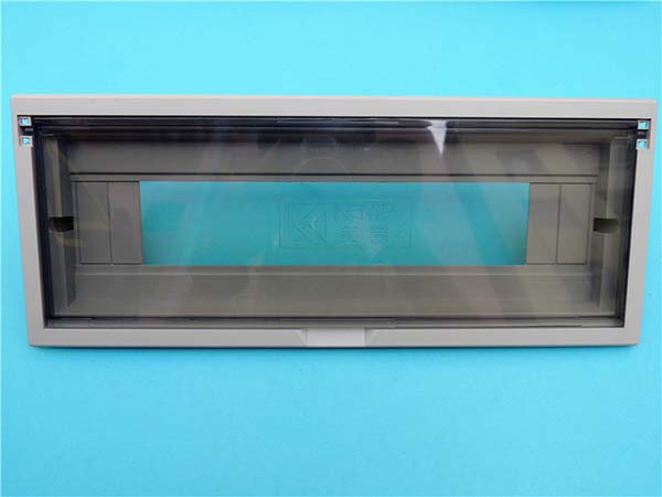
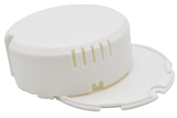
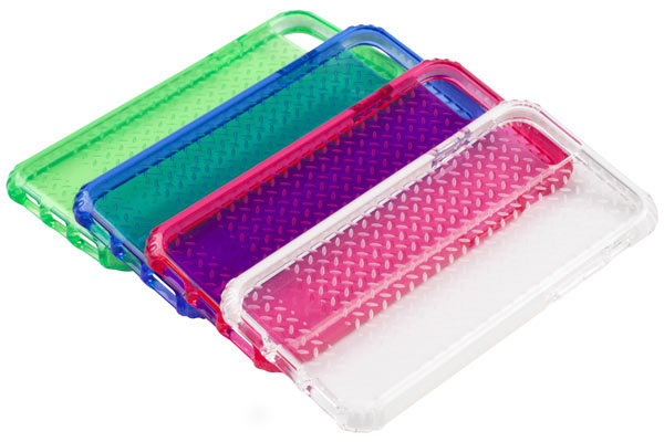
This process is not limited to plastics. It also works with metals (metal powder injection molding) and rubber. In the automotive industry, dashboards, bumpers, and interior trims are injection molded. In the medical field, syringes and device components are produced this way.
What Are the Key Components?
Injection Machine
Hopper: Stores raw material, usually in pellet form. It feeds material into the barrel at a controlled rate.
Screw: Rotates to convey, melt, and homogenize the material. Friction from rotation generates heat that helps melting.
Heating Unit: Surrounds the barrel to bring material to the correct melting temperature. Polyethylene (PE) melts at 110°C to 130°C . Polycarbonate (PC) melts at 220°C to 230°C .
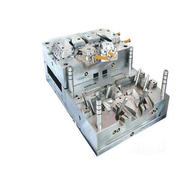
Mold
Stationary Mold Half: Attached to the machine’s stationary platen. It contains part of the cavity.
Moving Mold Half: Attached to the moving platen. It moves to close and open the mold.
Cavity: The hollow space that gives the part its shape. It is a direct representation of the finished product.
Core: Used to create internal features or holes. Material flows around it.
The table below summarizes key components:
| Component | Function |
|---|---|
| Hopper | Stores and feeds raw material |
| Screw | Conveys, melts, and homogenizes material |
| Heating Unit | Melts material by providing heat |
| Stationary Mold Half | Holds cavity, fixed to stationary platen |
| Moving Mold Half | Moves to close and open mold |
| Cavity | Determines external shape of part |
| Core | Creates internal features or holes |
Step 1: How to Select the Right Material?
Material selection is the foundation of a successful part. Several factors guide the choice.
End-Use Environment
If the part will be exposed to high temperatures, choose a material with high heat resistance. Polycarbonate (PC) has a heat deflection temperature of 130°C to 140°C at 1.82 MPa load. This makes it suitable for automotive lighting components.
Physical Property Requirements
Tensile strength matters for parts under pulling forces. Polypropylene (PP) has tensile strength of 30 to 40 MPa , suitable for containers that maintain shape under normal handling.
Cost
Polystyrene (PS) has relatively low cost. It is used for disposable items like plastic cutlery.
The table below compares common materials:
| Material | Melting Point (°C) | Tensile Strength (MPa) | Density (g/cm³) | Cost |
|---|---|---|---|---|
| LDPE | 105 – 115 | 7 – 15 | 0.91 – 0.94 | Low |
| HDPE | 125 – 135 | 20 – 35 | 0.94 – 0.97 | Low-Medium |
| PP | 160 – 170 | 30 – 40 | 0.90 – 0.91 | Medium |
| PS | 100 – 110 | 35 – 60 | 1.04 – 1.06 | Low |
| PC | 220 – 230 | 60 – 70 | 1.20 | High |
Step 2: How to Design and Prepare the Mold?
Mold design determines part quality. A well-designed mold ensures accurate dimensions and good surface finish.
Key Design Elements
Parting line: The boundary where mold halves separate. It should be placed to ensure easy ejection and minimize visible seams. On a plastic bottle, the parting line often runs around the circumference.
Gate: The opening where molten material enters the cavity. Pin gates suit small, precise parts. Edge gates and film gates work for other geometries.
Runner system: Distributes material from the injection nozzle to gates. It should minimize pressure loss and ensure uniform cavity filling.
Mold Design Process
- Product analysis: Examine the 3D model. Consider dimensions, tolerances, and features.
- Design for Manufacturing (DFM): Evaluate manufacturability. Suggest design improvements.
- Parting line determination: Decide location.
- Gate and runner design: Select gate type, size, and runner layout.
- Cooling system design: Plan channels for even cooling.
- Ejection system design: Design mechanism to remove part.
- Mold assembly design: Define how components fit together.
Mold Processing
High-precision machining creates the mold. CNC milling achieves tolerances within ±0.05 mm . EDM (Electrical Discharge Machining) creates complex shapes and fine details.
Mold assembly requires careful alignment. Bolts and dowel pins hold components together. Alignment should be within ±0.02 mm for optimal performance.
Step 3: How to Set Up and Calibrate the Machine?
Proper setup ensures consistent quality.
Temperature Settings
Barrel zones have different temperatures. For ABS:
- Rear zone: 170°C – 180°C
- Middle zone: 190°C – 200°C
- Front zone (near nozzle): 210°C – 220°C
Mold temperature affects part quality. Thin-walled parts may use 40°C to 50°C for quick cooling.
Pressure Settings
Injection pressure forces material into the cavity. Complex parts with long flow paths may need 100 to 150 MPa .
Holding pressure applies after filling to compensate for shrinkage. Typical range: 30 to 50 MPa .
Injection Speed
Speed affects filling quality. For medium-sized parts, 30 to 60 mm/s is appropriate.
The table below shows how parameters affect quality:
| Parameter | High Setting Effect | Low Setting Effect |
|---|---|---|
| Temperature | Degradation, overheating | Incomplete melting, poor flow, short shots |
| Injection Pressure | Flash, high internal stresses | Incomplete filling, weak weld lines |
| Injection Speed | Air traps, flow marks | Incomplete filling, long cycles |
Step 4: How Does Injection and Filling Work?
Molten material is forced through the nozzle, runner system, and gates into the cavity.
In a simple rectangular cavity, material flows in a wave-like pattern. In complex cavities with thin-walled sections, flow patterns are more intricate.
Pressure Maintenance and Shrinkage
After filling, material starts to cool and shrink. Holding pressure pushes additional material into the cavity to compensate. Without proper holding, parts develop sink marks or under-filled areas.
Step 5: How to Manage Cooling and Solidification?
Cooling determines dimensional stability and cycle time.
Cooling Time Calculation
Cooling time can be estimated with the formula:
t = h² / (4α)
Where:
- t = cooling time
- h = part thickness
- α = thermal diffusivity of the material
For a 3 mm thick part made of PP (thermal diffusivity about 1.1 × 10⁻⁷ m²/s ), cooling time can be calculated accordingly.
Factors Affecting Cooling
- Part thickness
- Mold material (copper alloy cools faster than steel)
- Coolant temperature
Uneven Cooling Defects
If cooling is not uniform, parts warp. If one side cools faster than the other, the part warps toward the cooler side.
Cooling Optimization
- Use baffles in cooling channels to improve flow and heat transfer
- Distribute cooling channels evenly around the cavity
Step 6: How to Eject and Remove the Part?
After solidification, the part must be ejected without damage.
Ejection Devices
Ejector pins: Small pins that push the part out. Placed in thick-walled sections or non-visible surfaces to avoid marks.
Ejector plates: Move all ejector pins simultaneously.
Ejection Force
Force must be carefully controlled. Too much force cracks the part. Too little leaves it stuck. The ejection sequence should push the part evenly.
Step 7: What Post-Processing Is Required?
Post-processing achieves final appearance and functionality.
Deburring: Removes excess material. Done manually with files or through chemical or abrasive methods.
Trimming: Removes small imperfections.
Surface treatment: Painting adds color and corrosion protection. Electroplating provides a metallic finish and wear resistance. Printing adds labels, logos, or markings.
What Does a Real-World Example Look Like?
A consumer goods company needed a new handheld device housing. The part had to be lightweight, impact-resistant, and aesthetically pleasing.
Material selection settled on ABS. It offered the right balance of strength, toughness, and surface finish. The mold design included a three-plate system with a pinpoint gate to hide the gate mark on an internal surface.
Cooling channels were placed strategically to ensure uniform cooling. Cycle time was optimized to 45 seconds. Ejector pins were placed in thick sections to avoid visible marks.
The finished parts passed drop tests and cosmetic inspections. The product launched on schedule and met sales targets.
Conclusion
Crafting parts for injection molding involves seven steps: material selection, mold design, machine setup, injection and filling, cooling, ejection, and post-processing.
Each step affects final quality. Material choice determines performance. Mold design dictates shape and precision. Machine settings control flow and cooling. Post-processing adds finish and functionality.
Success comes from attention to detail at every stage. When each step is executed correctly, injection molding delivers high-quality, consistent parts efficiently.
FAQ
What's the difference between injection molding and plastic injection molding?
Injection molding is the broader term. It includes injecting molten material—plastic, metal (in metal injection molding), rubber—into a mold cavity. Plastic injection molding is a subset that specifically deals with plastic materials. In everyday manufacturing language, the terms are often used interchangeably, but technically injection molding has a wider scope.
How to choose the right plastic material for injection molding?
Consider product performance requirements. For high strength, PC or ABS are suitable. PC offers high impact strength. ABS balances strength, toughness, and heat resistance. For flexibility, thermoplastic elastomers (TPEs) work well.
Consider processing performance. Materials with good flowability fill complex cavities easily. PE flows well for intricate shapes.
Consider cost. Commodity plastics like PE and PP are cost-effective for large-scale production. Engineering plastics like PC and PEEK cost more and are reserved for applications where performance outweighs cost concerns.
What causes warping in injection-molded parts?
Uneven cooling is the primary cause. When one section of a part cools faster than another, internal stresses develop. The part warps toward the cooler side. Solutions include redesigning cooling channels for uniform heat extraction, adjusting mold temperature, and ensuring uniform wall thickness in the part design.
How long does the injection molding process take?
Cycle time varies by part size and material. Small, thin-walled parts may cycle in 10 to 20 seconds . Large, thick parts may take 60 to 120 seconds . Cooling time dominates the cycle. Faster cooling reduces cycle time but risks internal stresses.
What is the role of holding pressure in injection molding?
Holding pressure is applied after the cavity is filled. As the material cools, it shrinks. Holding pressure pushes additional material into the cavity to compensate for shrinkage. Without proper holding pressure, parts develop sink marks, voids, or under-filled sections.
Contact Yigu Technology for Custom Manufacturing
At Yigu Technology , we specialize in injection molding for custom plastic and metal parts. Our engineers guide you through every step—material selection, mold design, process optimization, and post-processing.
We offer a wide range of materials and processing techniques. Our quality control system ensures consistent results from prototype to high-volume production.
Contact Yigu Technology today to discuss your injection molding project. Let us help you craft parts that meet your exact specifications.