Introduction
What is Injection Molding?
Injection molding is a manufacturing process that involves injecting molten material, typically plastic or metal, into a mold cavity. The material then cools and solidifies within the mold, taking on the shape of the cavity. This process is widely used for mass - production of parts with high precision and repeatability.
The history of injection molding dates back to the 19th century. It evolved from the metal casting process, and the first injection molding machine was developed in the early 20th century. Since then, the technology has advanced significantly, with the development of better materials, more precise machinery, and computer - aided design and manufacturing (CAD/CAM).
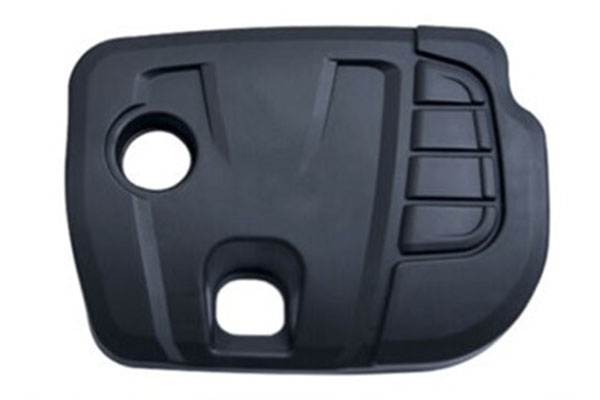
Injection molding is used in a wide range of industries. In the automotive industry, it is used to produce parts such as bumpers, dashboards, and interior trims. The electronics industry relies on injection molding for components like smartphone cases, computer keyboards, and electronic housings. The medical field uses it for items like syringes, medical device casings, and prosthetics. The global injection molding market size was valued at approximately $350 billion in 2023 and is expected to grow at a CAGR of around 5% from 2024 - 2030, driven by the growth in end - use industries and technological advancements.
Importance of Vent Design in Injection Molding
Vent design is a crucial aspect of injection molding. When the molten material is injected into the mold cavity, the air inside the cavity needs to escape. If there is no proper venting, air can become trapped, leading to several issues:
- Trapped Air Pockets: Trapped air pockets can cause voids or bubbles in the final product. These imperfections can weaken the structural integrity of the part and affect its appearance. For example, in the production of a plastic toy, a trapped air pocket can create a visible hole or a weak spot that may cause the toy to break easily.
- Weld Lines: Inadequate venting can result in poor fusion of the molten material, leading to the formation of weld lines. Weld lines occur when two streams of molten plastic meet during the injection process. If air is trapped, the weld lines may be more pronounced, reducing the strength and aesthetics of the product.
- High Pressure and Temperature Buildup: Trapped air can be compressed during the injection process, leading to a buildup of pressure and temperature. This can cause the molten material to overheat, resulting in charring or degradation of the material. In extreme cases, it can even damage the mold.
- Incomplete Filling: Without proper venting, the air in the cavity can act as a barrier, preventing the molten material from completely filling the mold cavity. This can lead to incomplete parts and high rejection rates.
A well - designed vent system allows the air to escape smoothly, ensuring that the molten material fills the mold cavity evenly. It helps in producing high - quality parts with consistent dimensions, better surface finish, and improved mechanical properties. In short, vent design is essential for the success of the injection molding process and the quality of the final products.
Key Elements of Injection Molding Vent Design
Vent Location
Determining the vent location is a critical step in injection molding vent design. The main factors to consider include the plastic melt flow direction and the cavity shape.
Melt Flow Direction: The vents should be placed at the end of the melt flow path. When the molten plastic is injected into the mold, it pushes the air in front of it. By placing the vents at the end of the flow path, the air can escape smoothly. For example, in the injection molding of a long - rectangular plastic part, if the melt is injected from one short side, the vents should be located on the opposite short side. If the vents are placed in the middle of the long side, air may get trapped in the corners, resulting in voids or incomplete filling.
Cavity Shape: Complex - shaped cavities require careful consideration of vent location. In a cavity with multiple recesses or protrusions, air can become trapped in these areas. For instance, in a mold with a cavity in the shape of a letter "T", the intersection of the vertical and horizontal parts is a high - risk area for air entrapment. Vents should be placed at the end of each branch of the "T" to ensure proper air escape.
If the vent location is incorrect, it can lead to serious problems. A case study showed that in the production of a plastic automotive interior component, the vents were placed too close to the injection point. As a result, the air was not able to escape fast enough, and large voids were found in the final product. This led to a high rejection rate and increased production costs.
Vent Size
The size of the vents is another crucial aspect. It depends on several factors, such as the type of material being used and the size of the product.
Material - Dependent Sizes: Different materials have different viscosities and flow characteristics. For low - viscosity materials like polyethylene (PE), the vents can be relatively smaller. A general rule of thumb is that for PE, the vent width can be around 0.02 - 0.03 mm, and the depth can be 0.02 - 0.05 mm. For high - viscosity materials such as polycarbonate (PC), larger vents are required. The vent width for PC might be in the range of 0.03 - 0.05 mm, and the depth can be 0.05 - 0.08 mm.
Product - Size Considerations: Larger products usually require larger vents. A small plastic toy might have vents with a width of 0.02 mm and a depth of 0.03 mm. In contrast, a large plastic storage bin may need vents with a width of 0.05 mm and a depth of 0.08 mm to allow sufficient air to escape during the injection process.
The following table summarizes the vent size ranges for some common materials:
| Material | Vent Width (mm) | Vent Depth (mm) |
| Polyethylene (PE) | 0.02 - 0.03 | 0.02 - 0.05 |
| Polypropylene (PP) | 0.02 - 0.04 | 0.03 - 0.06 |
| Polycarbonate (PC) | 0.03 - 0.05 | 0.05 - 0.08 |
| Acrylonitrile Butadiene Styrene (ABS) | 0.02 - 0.04 | 0.03 - 0.07 |
If the vent size is too small, the air will not be able to escape quickly enough, leading to trapped air issues. On the other hand, if the vent size is too large, the molten plastic may leak out of the vents, which is called "flash".
Vent Type
There are several common types of vents in injection molding, each with its own advantages and disadvantages.
(Parting Line Vents): These vents are located at the parting line of the mold. They are easy to machine and are suitable for many applications. However, if not properly designed, they can cause flash on the parting line of the final product.
(Insert Vents): Insert vents use small inserts with grooves or holes to allow air to escape. They are useful for areas where traditional parting line vents are not feasible. But they can be more difficult to install and maintain, and there may be a risk of the insert becoming dislodged during the molding process.
(Ejector Pin Vents): Ejector pin vents utilize the small gaps between the ejector pins and the mold to vent air. They are convenient as they are integrated with the ejection system. However, the venting area provided by ejector pin vents may be limited, especially for small ejector pins.
The following table compares the different vent types:
| Vent Type | Advantages | Disadvantages |
| Parting Line Vents | Easy to machine, suitable for many applications | Can cause flash on the parting line |
| Insert Vents | Useful for areas where other vents are not feasible | Difficult to install and maintain, risk of insert dislodgment |
| Ejector Pin Vents | Convenient as they are integrated with the ejection system | Limited venting area, especially for small ejector pins |
Choosing the right vent type depends on the specific requirements of the injection molding project, such as the product design, the complexity of the mold, and the production volume.
Design Process and Considerations
Analyzing the Part Design
Before starting the vent design, a detailed analysis of the part design is crucial. Complex - shaped parts, especially those with thin walls, deep recesses, or intricate geometries, require more careful vent design considerations. For example, in the injection molding of a plastic electronic component with multiple small cavities and thin - walled sections, the air has more difficulty escaping. The areas with sharp corners and narrow passages are more likely to trap air. By thoroughly examining the part design, mold makers can identify these high - risk areas and plan the venting accordingly. They can determine the optimal number of vents, their locations, and sizes based on the part's geometry. A part with a large, flat surface may require multiple evenly - spaced vents along the perimeter to ensure uniform air escape. In contrast, a part with a long, narrow channel may need vents at the end of the channel and at any points where the cross - section changes significantly.
Mold Flow Analysis
Mold flow analysis software has become an essential tool in modern injection molding vent design. Software such as Moldflow by Autodesk allows mold makers to simulate the injection molding process virtually.
During the mold flow analysis, the software can predict the melt flow front, temperature distribution, and air entrapment areas within the mold cavity. The analysis results are presented in visual formats, such as colored contour maps. For example, areas where air is likely to be trapped are often highlighted in a specific color, such as red. These visualizations help mold makers to understand the air movement during the injection process clearly.
Based on the mold flow analysis results, mold makers can make informed decisions to optimize the vent design. If the analysis shows that air is likely to be trapped in a particular corner of the mold cavity, a vent can be added in that area. They can also adjust the vent sizes and locations to improve the air - escape efficiency. For instance, if the analysis indicates that the air is not escaping fast enough through a particular vent, the size of that vent can be increased.
Material Considerations
Different injection - molding materials have distinct properties that significantly impact vent design. One of the key factors is the material's viscosity or flowability.
Low - viscosity materials, like polyethylene (PE), flow more easily during the injection process. They can displace air more efficiently, so they generally require smaller vents. As mentioned before, for PE, the vent width can be around 0.02 - 0.03 mm, and the depth can be 0.02 - 0.05 mm. On the other hand, high - viscosity materials such as polycarbonate (PC) are more resistant to flow. They need larger vents to ensure that the air can escape before the molten material fills the cavity. The vent width for PC might be in the range of 0.03 - 0.05 mm, and the depth can be 0.05 - 0.08 mm.
In addition to viscosity, the shrinkage rate of the material also affects vent design. Materials with a high shrinkage rate may cause the part to pull away from the mold during cooling, creating voids if not properly vented. For such materials, vents need to be designed to allow air to re - enter the cavity during the cooling process to prevent these voids from forming.
Yigu Technology's Perspective
As a non - standard plastic metal products custom Supplier, Yigu Technology has rich experience in vent design for injection molding. We understand that effective vent design is crucial for producing high - quality products with minimal defects.
In the initial stage of each project, we place great emphasis on in - depth communication with clients. By fully understanding their product requirements, material choices, and production expectations, we can lay a solid foundation for a successful vent design. This early - stage communication helps us to identify potential issues related to venting and come up with tailored solutions.
Yigu Technology also makes use of advanced simulation technologies. We employ state - of - the - art mold flow analysis software to predict the behavior of molten materials during injection. This allows us to optimize the vent design in terms of location, size, and type. For example, through simulation, we can accurately identify areas where air is likely to be trapped and then design vents specifically for those areas. This not only improves the quality of the final products but also reduces the need for costly trial - and - error during the actual production process. Our focus on using technology and communication ensures that our vent designs meet the highest standards of the industry.
FAQs
What is the most common mistake in injection molding vent design?
The most common mistake in injection molding vent design is improper vent location. If vents are not placed at the end of the melt flow path or in areas where air is likely to be trapped, it can lead to serious product quality issues. For example, air pockets may form within the product, resulting in voids or bubbles that weaken the structural integrity. In some cases, trapped air can cause incomplete filling of the mold cavity, leading to parts that do not meet the required specifications. Additionally, incorrect vent location can contribute to the formation of weld lines, which can affect the aesthetics and strength of the final product.
How can I tell if my injection molding vent design is working?
There are several ways to determine if your injection molding vent design is working effectively. First, visually inspect the products. A well - designed vent system should result in products with a smooth surface finish, free of voids, bubbles, or visible weld lines. If you notice these defects, it may indicate a problem with the vent design. Second, you can perform non - destructive testing, such as ultrasonic testing, to check for internal voids or defects that are not visible on the surface. Another method is to use mold flow analysis software during the design stage and compare the actual results with the simulated ones. If the actual product shows similar air - escape patterns and filling behaviors as predicted by the software, it's a good sign that the vent design is working as intended.
Can the vent design affect the production cycle time?
Yes, the vent design can significantly affect the production cycle time. If the vents are too small or not properly located, air may not escape quickly enough during the injection process. This can lead to a longer filling time as the molten material has to push against the trapped air. Additionally, trapped air can cause the molten material to cool unevenly, increasing the cooling time required for the part to solidify. In some cases, improper venting can result in defects that require the part to be re - molded, further increasing the production cycle time. On the other hand, a well - designed vent system allows for faster air escape, enabling quicker filling and potentially reducing the overall production cycle time.