Introduction
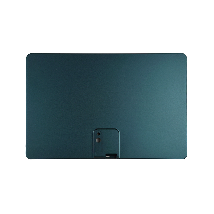
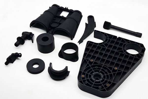
Walk onto any factory floor that makes plastic parts, and you’ll see them: rows of injection moulding machines, each quietly humming through cycle after cycle. These machines turn piles of plastic pellets into finished products—everything from bottle caps to car bumpers—in seconds.
But what’s inside those machines? How do they convert raw material into precision parts with such consistency?
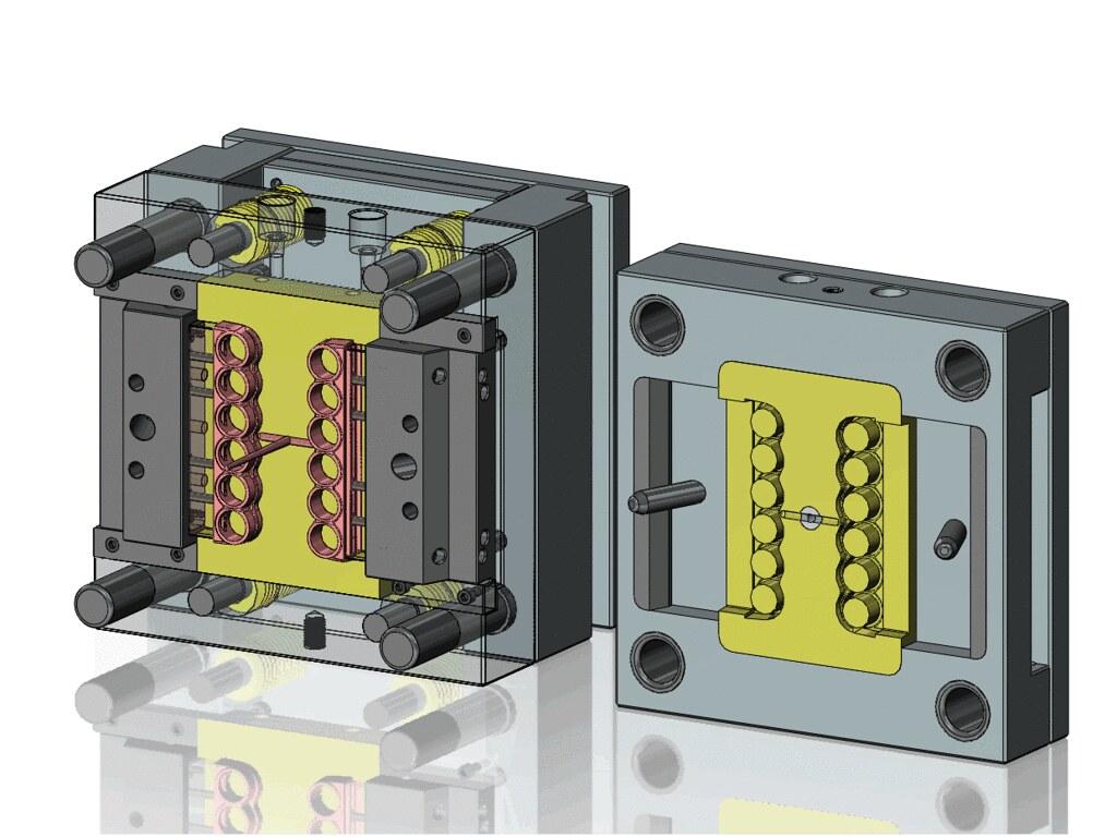
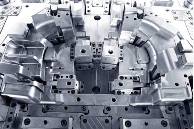
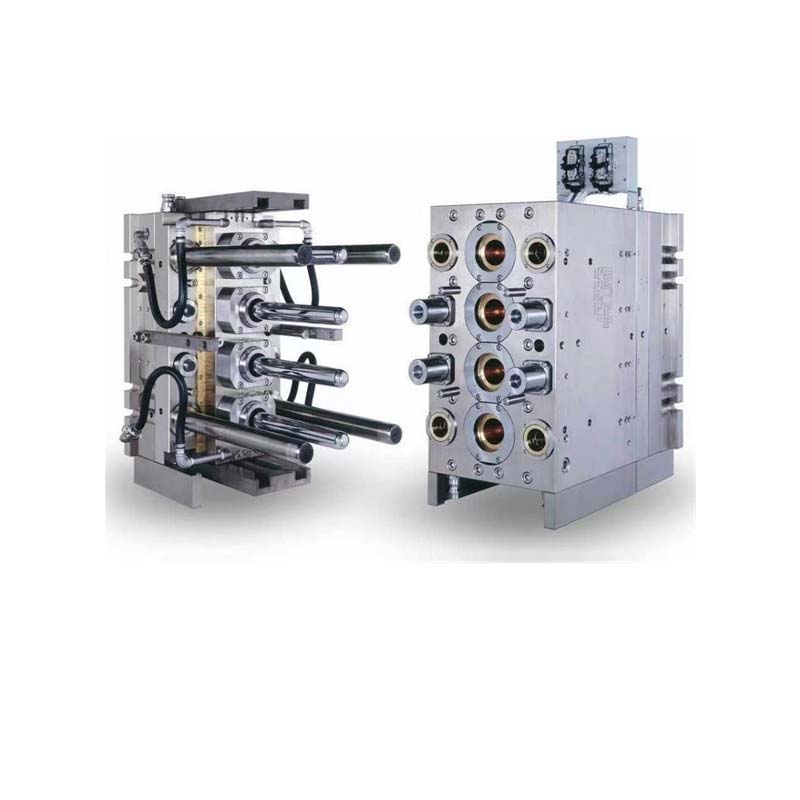
The answer lies in their components. An injection moulding machine is a carefully orchestrated system of parts, each with a specific job. The injection unit melts and moves the plastic. The clamping unit holds the mold shut under immense force. The control unit coordinates everything. And auxiliary systems keep it all running smoothly.
At Yigu Technology, we work with these machines daily, producing custom plastic and metal components for demanding applications. Understanding these components isn’t just technical trivia—it’s essential for anyone who designs, buys, or manufactures plastic parts. In this guide, we’ll break down each component, explain what it does, and show you why it matters.
What Does the Injection Unit Do?
The injection unit has one job: turn solid plastic pellets into a molten, pressurized stream ready to fill a mold. It’s where the material transforms.
The Screw
The screw is the heart of the injection unit. It rotates inside the barrel, pushing plastic pellets forward while melting them through a combination of shear heat and external heating.
Screws come in different designs for different materials:
| Screw Type | Best For | Key Feature |
|---|---|---|
| General-purpose | Polyethylene, polypropylene | Simple constant-pitch design |
| Barrier screw | PVC, other difficult-to-melt polymers | Separates solid and molten plastic for uniform melting |
| High-compression screw | Glass-filled plastics | Large groove depth difference for better compaction |
A poorly chosen screw leads to inconsistent melt, which leads to defective parts. For example, glass-filled nylon requires a screw with abrasion-resistant coatings—otherwise, the glass fibers wear down the screw in months instead of years.
The Barrel
The barrel surrounds the screw. It provides the confined space where melting happens. Barrels are made from high-strength alloy steel—often grades like 38CrMoALA—to withstand temperatures up to 400°C and pressures exceeding 200 MPa.
Heating bands wrap around the barrel, divided into zones. Each zone has its own temperature controller. For polycarbonate, the barrel might be set to 250–320°C. For polystyrene, 180–260°C. Precise zoning ensures the plastic melts gradually, not all at once.
Some barrels also have cooling channels near the feed throat. This prevents pellets from melting too early and clogging the inlet.
The Nozzle
The nozzle sits at the end of the barrel. It’s the last stop before molten plastic enters the mold.
| Nozzle Type | Advantage | Disadvantage |
|---|---|---|
| Open-ended | Simple, low cost, high flow | Can drool plastic between cycles |
| Shut-off | Prevents drooling, clean injection | More complex, needs maintenance |
| Hot-runner nozzle | No waste, ideal for multi-cavity molds | Higher upfront cost |
Real-world example: A Yigu Technology client producing medical syringe components needed zero contamination between cycles. We switched from an open-ended nozzle to a shut-off nozzle, eliminating drool and reducing scrap by 8% in the first month.
How Does the Clamping Unit Work?
The clamping unit holds the mold closed during injection. It must generate enough force to keep the mold halves from separating under injection pressure.
Toggle Mechanisms
Many machines use a toggle mechanism—a system of linked arms that amplifies force. A small hydraulic cylinder moves the links. When the links straighten, they multiply the input force by a factor of 10 to 30 times.
Toggle systems are compact and fast. They’re common in smaller machines—up to about 500 tons of clamping force. For high-speed applications like thin-wall packaging, toggles can cycle in under two seconds.
Hydraulic Cylinders
Larger machines—especially those over 500 tons—often use direct hydraulic clamping. A hydraulic cylinder pushes the moving plate directly.
The force comes from Pascal’s principle: (F = P \times A). With a piston diameter of 200 mm and hydraulic pressure of 150 bar (15 MPa), a single cylinder generates over 470,000 Newtons—about 47 tons of force.
Hydraulic clamping offers flexible force profiles. You can program different clamping forces during the cycle—high force during injection, lower force during cooling—which helps with venting and reduces mold wear.
Moving and Fixed Plates
The mold mounts on two plates. The fixed plate stays stationary, bolted to the machine frame. The moving plate slides on guides, pushed by the clamping mechanism.
These plates must be massive and precise. Any deflection under clamping force causes uneven mold closure, leading to flash or inconsistent wall thickness. In automotive-grade machines, plates are often cast iron or forged steel, machined flat to within 0.01 mm.
What Does the Control Unit Manage?
Modern injection moulding machines are computers with hydraulic or electric muscles. The control unit orchestrates every movement.
Programmable Logic Controller (PLC)
The PLC is the machine’s brain. It’s a rugged industrial computer that executes the molding cycle step by step.
The PLC controls:
- Screw rotation speed and position
- Injection speed and pressure profiles
- Clamp open/close speeds
- Temperature zones in barrel and mold
- Ejector timing and force
In automated factories, PLCs network together. A central system can monitor 100+ machines, tracking cycle times, temperatures, and alarms. If a machine drifts out of spec, the PLC can adjust parameters automatically—or alert an operator.
Human-Machine Interface (HMI)
The HMI is how operators talk to the machine. It’s usually a touchscreen that displays real-time data and accepts inputs.
Operators use the HMI to:
- Set parameters: injection pressure, speed, temperatures, cooling time
- Monitor status: current cycle phase, temperatures, pressures
- View alarms: fault messages with troubleshooting guidance
A well-designed HMI reduces setup time. Instead of hunting through paper manuals, operators tap a screen to load saved recipes for each product. This cuts changeover time from hours to minutes.
What Auxiliary Components Keep It Running?
The main components do the work, but auxiliary systems keep them working reliably.
Cooling System
Cooling accounts for 70–80% of cycle time. Efficient cooling means faster cycles and higher output.
Water cooling is most common. Coolant circulates through channels drilled into the mold. The heat exchanger—a cooling tower or chiller—removes heat before returning the water to the mold.
For precision parts, oil cooling offers tighter temperature control. Oil has higher thermal stability, making it suitable for molds that must stay within a narrow temperature range—like optical lenses.
Air cooling exists but is much less efficient. It’s only used for very small molds or low-volume production.
Lubrication System
Moving parts need lubrication. Without it, wear accelerates and failures multiply.
Key lubrication points:
- Toggle joints (grease)
- Guide rails (oil)
- Ejector pins (light oil)
Automatic lubrication systems pump measured amounts at set intervals. They’re standard on modern machines because they eliminate the guesswork—and missed lubrication—of manual methods.
Safety Devices
Injection moulding machines can be dangerous. Hot surfaces, moving platens, and high-pressure hydraulics all pose risks.
Safety doors are interlocked. Open the door during a cycle, and the machine stops immediately.
Emergency stop buttons—bright red, strategically placed—cut power to all motion systems when pressed.
Light curtains create invisible barriers. If anything breaks the beam—like a hand reaching into the clamping area—the machine halts.
These systems aren’t optional. They’re required by safety standards like OSHA in the US and CE in Europe.
How Does Yigu Technology Use This Knowledge?
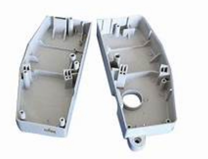
As a custom manufacturer of non-standard plastic and metal products, we don’t just buy machines—we spec them for each application.
For a recent project involving glass-filled nylon components, we selected a machine with:
- A bimetallic barrel and abrasion-resistant screw to withstand glass fiber wear
- A shut-off nozzle to prevent drool during high-cycle production
- A hydraulic clamping system for precise force control on a complex mold
The result? The mold ran for 500,000 cycles with no significant screw wear—compared to an estimated 150,000 cycles with a standard screw.
We also rely heavily on control system data. Every machine logs cycle parameters. When a customer reports a quality issue, we trace it back to the exact cycle—temperature, pressure, speed—and identify the root cause. That level of traceability is essential for medical and automotive applications.
Conclusion
An injection moulding machine is more than a box that makes plastic parts. It’s a system of carefully integrated components, each with a critical role.
The injection unit melts and moves the material. The clamping unit holds the mold shut under immense force. The control unit orchestrates every action with precision. Auxiliary systems—cooling, lubrication, safety—keep everything running reliably.
Understanding these components helps you make better decisions. When you know what the screw does, you understand why material selection matters. When you know how the clamping unit works, you appreciate why mold design affects machine size. And when you see the control system in action, you realize how process data drives quality.
Whether you’re designing a new part, buying a machine, or troubleshooting production, this knowledge pays off.
FAQ
What are the main components of an injection moulding machine?
The three primary components are the injection unit (screw, barrel, nozzle), the clamping unit (toggle or hydraulic system, moving and fixed plates), and the control unit (PLC and HMI). Auxiliary systems like cooling, lubrication, and safety devices support these main components.
How does the screw affect part quality?
The screw controls how uniformly the plastic melts. A poorly designed or worn screw creates inconsistent melt temperature and viscosity. This leads to defects like short shots (incomplete filling), sink marks, and burn marks. For demanding materials like glass-filled or heat-sensitive plastics, specialized screw designs are essential.
What is the difference between toggle and hydraulic clamping?
Toggle clamping uses a mechanical linkage to amplify force. It’s compact and fast, making it ideal for smaller machines and high-speed applications. Hydraulic clamping uses a hydraulic cylinder directly. It offers more flexible force control and is common on larger machines (over 500 tons). Both systems work well when properly matched to the application.
Why is the control unit important for quality?
The control unit—specifically the PLC and HMI—ensures every cycle runs exactly the same. It maintains temperatures, pressures, speeds, and timing within set ranges. Modern controls also collect data, allowing manufacturers to trace defects back to specific cycles and continuously optimize processes.
What safety devices are required on injection moulding machines?
Key safety devices include safety doors interlocked with the machine’s operation, emergency stop buttons that halt all motion, and light curtains that detect intrusion into hazardous areas. These are mandated by international safety standards and are essential for operator protection.
Contact Yigu Technology for Custom Manufacturing
Need a custom plastic or metal component? At Yigu Technology, we combine deep knowledge of injection moulding equipment with hands-on manufacturing experience. We help clients select the right materials, design for manufacturability, and produce high-quality parts at scale.
From medical devices to automotive components, we’ve built our reputation on reliability and precision. Contact us today to discuss your project—and let us put our expertise to work for you.