Introduction
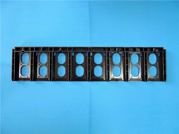
Injection molding produces the plastic parts that surround us. But every molded part carries marks—visible indicators of how it was made. These marks are not defects in themselves. They are clues. They tell you about the process, the material, and potential quality issues.
Learning to identify these marks is essential for manufacturers. A sink mark near a thick section warns of uneven cooling. A weld line in a critical area signals potential weakness. A flow mark indicates improper injection speed or gate design.
This guide walks you through common injection molding marks—sink marks, weld lines, flow marks, jetting marks—their causes, and how to identify them. You will also learn how material, process, and mold factors affect mark formation.
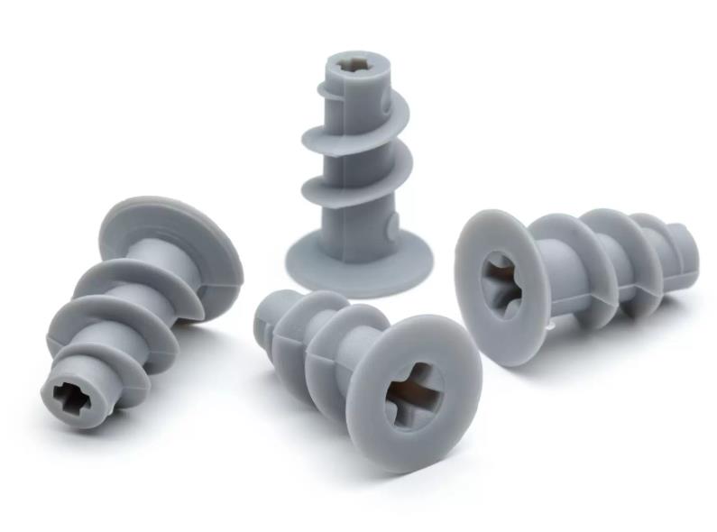
What Are Sink Marks?
Sink marks appear as small depressions or pits on the surface of a molded part. They are one of the most common defects in injection molding.
Causes
Sink marks occur when thick-walled sections cool more slowly than surrounding thinner areas. As the thick section shrinks, the surface sinks inward.
A plastic toy with a thick handle and thin body will likely show sink marks on the handle. The handle cools slower and shrinks more.
Other causes include:
- Insufficient holding pressure
- Improper cooling system design
- Poor gate placement
How to Identify
Look for smooth, concave areas on the surface. These are usually circular or oval. They often appear near:
- Thick-walled sections
- Bosses
- Ribs
In good lighting, sink marks are visible. If they are subtle, run your finger over the surface. You will feel the depression.
What Are Weld Lines?
Weld lines—also called knit lines—occur when two or more streams of molten plastic meet and fuse together in the mold cavity. They appear as lines on the part surface.
Causes
During injection, plastic melt flows through different channels. It may converge around:
- Inserts
- Complex cavity shapes
- Multiple gate locations
A plastic housing with an internal partition may have two melt streams meeting at the partition, forming a weld line.
Impact on Products
Weld lines reduce mechanical strength. Parts may break under stress at the weld line. Appearance is also affected—the line may be visible as a distinct mark or texture change.
How to Identify
Look for a linear mark on the surface. The color and texture at the weld line may differ from surrounding material. The line may be slightly raised or depressed.
Under magnification, you can observe different molecular orientation at the weld line. The plastic did not fully intermix at the meeting point.
What Are Flow Marks?
Flow marks are streaks or lines on the surface that follow the direction of plastic flow during injection.
Causes
Flow marks result from uneven flow of the plastic melt. Common causes:
- Improper gate design (gate too small)
- High injection speed
- Low melt temperature
A gate that is too small causes high shear stress. The plastic experiences uneven flow, leaving marks on the surface.
How to Identify
Flow marks appear as parallel or wavy lines on the surface. They are most prominent near the gate or along the main flow path. They affect surface finish, making the part look less smooth.
What Are Jetting Marks?
Jetting marks occur when molten plastic is injected into the mold cavity at high speed. The high-velocity jet hits the far wall first, then spreads out like splashing water.
Causes
Jetting happens when:
- Injection speed is too high
- Melt viscosity is too low
- Gate size is small relative to cavity size
The plastic shoots from the gate, hits the opposite mold wall, and spreads irregularly, leaving marks.
How to Identify
Look for a circular or fan-shaped pattern of streaks starting from the gate area. Marks are concentrated near the gate and fade with distance. The textured area feels rougher than surrounding surface.
How Do Material Factors Affect Marks?
Fluidity
Different plastics have different fluidity. Polyethylene (PE) flows easily. Polycarbonate (PC) has lower fluidity.
Higher fluidity reduces flow-related marks. A study showed that material with MFI 20 g/10min had only 10% flow mark occurrence . With MFI 5 g/10min , occurrence rose to 30% .
Shrinkage Rate
High-shrinkage materials are more likely to cause sink marks. Polypropylene (PP) shrinks 1% to 2% . A thick-walled PP product with uneven cooling can develop sink marks up to 0.5 mm deep .
The table below summarizes material effects:
| Material Property | Effect on Marks |
|---|---|
| High fluidity | Reduced flow marks, jetting marks |
| Low fluidity | Increased flow marks, weld lines |
| High shrinkage | Increased sink marks |
How Do Process Factors Affect Marks?
Injection molding parameters directly affect mark formation.
| Parameter | Low Setting Effect | High Setting Effect |
|---|---|---|
| Melt temperature | High viscosity → flow marks, weld lines | Low viscosity → jetting marks, possible degradation |
| Injection pressure | Incomplete filling, weld lines | Flash, stress, warping, sink marks |
| Injection speed | Flow marks, weld lines from uneven cooling | Jetting marks, trapped gas marks |
For ABS:
- Low melt temperature (180°C): increased flow marks
- High melt temperature (240°C): reduced viscosity, but risk of jetting if speed is too high
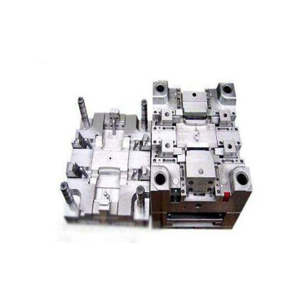
How Do Mold Factors Affect Marks?
Gate Location
Gate position affects plastic flow. If the gate is too far from a thin-walled area, plastic may not reach it properly. Incomplete filling and weld lines result.
In one mold design, original gate position (A) caused significant flow marks and weld lines. After optimization (B), flow became uniform and marks were greatly reduced.
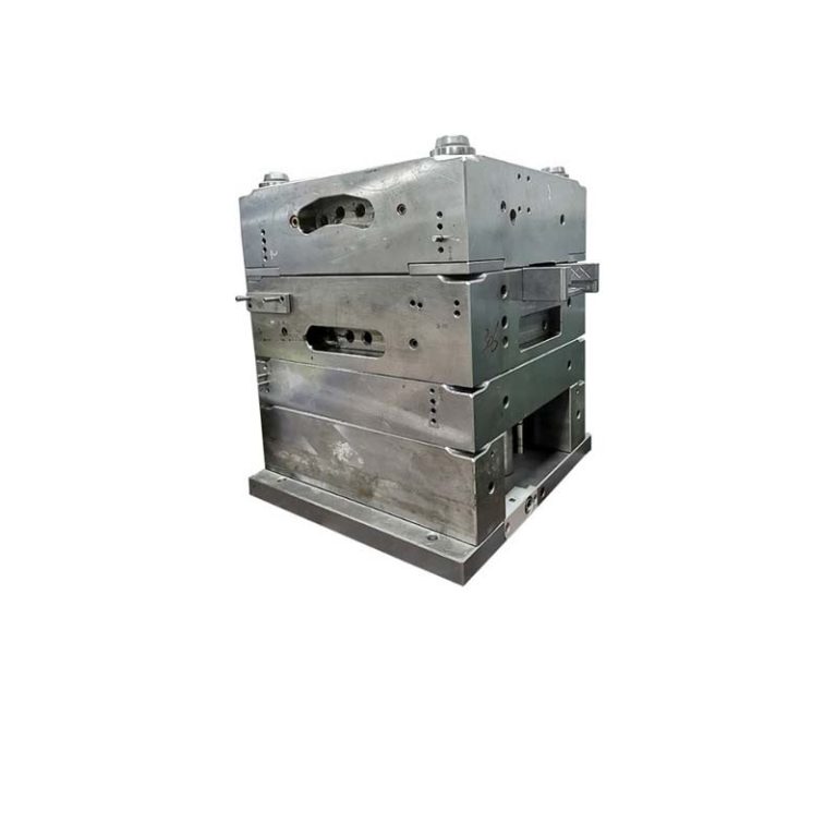
Runner System
A well-designed runner ensures even melt distribution. Narrow or uneven runners cause different flow resistances. High shear stress in narrow sections can overheat the melt, forming flow marks.
Optimizing runner diameter and transitions improves flow and reduces marks.
How to Reduce Injection Molding Marks?
Reduce Sink Marks
- Design uniform wall thickness
- Add cooling channels near thick sections
- Increase holding pressure
- Optimize gate placement to feed thick sections first
Reduce Weld Lines
- Adjust gate position for uniform flow
- Increase melt temperature for better fusion
- Increase injection speed to reduce cooling before meeting
- Add a weld line enhancer additive
Reduce Flow Marks
- Optimize gate size (larger gates reduce shear)
- Reduce injection speed
- Increase melt temperature
- Improve runner system design
Reduce Jetting Marks
- Reduce injection speed
- Increase melt temperature
- Use a larger gate
- Use a gate design that redirects flow (e.g., fan gate)
What Does a Real-World Example Look Like?
A manufacturer of ABS electronic housings faced weld line issues. The weld line appeared on a critical structural area. Parts failed drop tests at the weld line.
Investigation showed the gate was placed at one end of the cavity. Two melt streams met at the middle, forming a weld line exactly where stress concentrated.
The solution: relocate the gate to the center of the cavity. This created a single melt front that filled from the center outward. No weld line formed in the stress area.
Melt temperature was increased from 210°C to 230°C to improve flow. Injection speed was reduced slightly to prevent jetting.
Drop test failure rate dropped from 15% to under 1% .
Conclusion
Injection molding marks are not random. They are messages from the process. Sink marks point to uneven cooling and thick sections. Weld lines reveal where melt fronts meet. Flow marks indicate flow issues. Jetting marks signal excessive injection speed.
Identifying these marks requires visual inspection and sometimes touch. Understanding their causes—material, process, mold—helps you address root issues.
By recognizing marks and adjusting accordingly, you can improve part quality, reduce scrap, and optimize production.
FAQ
What are the common causes of sink marks in injection molding?
Non-uniform wall thickness is the primary cause. Thick sections cool slower and shrink more than thin sections, creating depressions. Improper cooling system design and insufficient holding pressure also contribute. Solutions include uniform wall thickness design, optimized cooling channels, and increased holding pressure.
How can I reduce the appearance of weld lines in my injection-molded parts?
Adjust gate position for more uniform plastic flow. Increase melt temperature to improve fusion. Increase injection speed to reduce cooling before melt fronts meet. For critical areas, design gates to eliminate weld lines or move them to non-stress locations. Adding weld line enhancer additives can also help.
Can flow marks be completely eliminated in injection molding?
Flow marks are difficult to eliminate completely because they are inherent to plastic flow. However, they can be greatly reduced. Optimize gate size and runner design. Reduce injection speed. Increase melt temperature. Well-designed molds and proper parameters can make flow marks barely visible.
What is the difference between a weld line and a flow mark?
A weld line forms where two melt streams meet and fuse. It appears as a line crossing the flow direction. A flow mark forms along the flow direction due to uneven flow. Weld lines can reduce mechanical strength. Flow marks primarily affect appearance.
How does melt temperature affect injection molding marks?
Low melt temperature increases viscosity, causing flow marks and weld lines. High melt temperature reduces viscosity, improving flow and reducing these marks. However, excessive temperature can cause jetting marks and material degradation. Balance is key—high enough for flow, low enough to prevent degradation.
Contact Yigu Technology for Custom Manufacturing
At Yigu Technology , we identify and solve injection molding mark issues daily. Our engineers analyze part designs before mold fabrication, optimizing wall thickness and gate placement to prevent marks. We use simulation software to predict flow and cooling behavior.
Our process parameters are tuned for each material and part geometry. We monitor and adjust to minimize sink marks, weld lines, flow marks, and jetting marks.
The result is high-quality parts with consistent appearance and strength.
Contact Yigu Technology today to discuss your injection molding project.