Introduction
When an aircraft takes off, thousands of components work together in perfect harmony. Many of those components—from interior panels to engine system parts—are made through aerospace injection molding.
This isn’t ordinary plastic manufacturing. Aerospace components face extreme conditions: high temperatures, aggressive chemicals, constant vibration, and weight constraints where every gram matters. The injection molding process for aerospace must deliver parts that meet strict safety standards, maintain tight tolerances, and perform reliably for decades.
At Yigu Technology, we’ve produced injection-molded components for aerospace applications ranging from cabin interiors to structural elements. In this guide, we’ll walk through the materials, design considerations, and process controls that make aerospace injection molding different—and how designers can get it right.
What Makes Aerospace Injection Molding Unique?
Aerospace injection molding follows the same basic process as general-purpose molding: melt plastic, inject into a mold, cool, and eject. But the requirements at every step are more demanding.
Precision: Aerospace parts often require tolerances of ±0.001 inches (0.025mm) or tighter. A connector housing that’s off by a fraction of a millimeter can cause system failures.
Material performance: Components must withstand temperatures from -60°C to 260°C, resist hydraulic fluids and fuels, and maintain strength under constant vibration.
Weight: Every gram matters. Replacing metal with high-performance plastic can reduce weight by up to 30% in some applications—directly improving fuel efficiency.
Regulatory compliance: Aerospace components must meet standards like FAA flammability requirements, outgassing limits (critical for sealed spacecraft environments), and strict traceability.
What Materials Are Used in Aerospace Injection Molding?
Material selection is the most critical decision in aerospace injection molding. Not all plastics can handle the demands of flight.
High-Performance Thermoplastics
| Material | Key Properties | Typical Aerospace Applications |
|---|---|---|
| PEEK | Continuous use to 260°C, excellent chemical resistance, high strength-to-weight | Engine components, fasteners, electrical connectors, pump housings |
| PEI (Ultem) | Flame resistance, low smoke, good mechanical properties at high temperatures | Interior components, ducting, structural brackets |
| PPS | Excellent chemical resistance, dimensional stability, high heat deflection | Fuel system components, valves, sensors |
| PC | Impact resistance, optical clarity, dimensional stability | Window frames, lighting covers, instrument panels |
| PA (Nylon) | Good strength, wear resistance, self-lubricating | Gears, bushings, cable clamps |
PEEK: The Aerospace Workhorse
PEEK (Polyether Ether Ketone) deserves special attention. It’s one of the few polymers that can replace metal in demanding aerospace applications.
- Temperature resistance: Continuous use at 260°C; short-term exposure to 300°C
- Chemical resistance: Unaffected by jet fuel, hydraulic fluids, and most solvents
- Strength: Tensile strength up to 100 MPa (unreinforced) and over 150 MPa with glass or carbon fiber
- Weight: Roughly one-fifth the density of steel
Real-world example: A fastener made from PEEK replaces a steel fastener weighing 10 grams. On an aircraft with 10,000 such fasteners, that’s 100 kg weight reduction—translating to significant fuel savings over the aircraft’s life.
Material Trade-offs
Choosing the right material means balancing performance against cost and processability.
| Material | Cost | Process Difficulty | Best Use Case |
|---|---|---|---|
| PEEK | High | High (high melt temp, viscosity) | Extreme environments, metal replacement |
| PEI | Medium-High | Moderate | Interior components, flame-resistant parts |
| PC | Moderate | Easy | Transparent parts, impact-resistant housings |
| Nylon | Low-Moderate | Moderate | Wear components, low-cost structural parts |
How Should Designers Approach Aerospace Parts?
Design for manufacturability (DFM) is essential. Aerospace parts often have complex geometries, and mistakes in design lead to costly mold modifications or production delays.
Wall Thickness
Wall thickness affects strength, weight, cooling time, and part quality. Uneven walls cause sink marks, internal voids, and warpage.
General guidelines:
| Material | Minimum Wall (mm) | Maximum Wall (mm) |
|---|---|---|
| PE | 0.9 | 4.0 |
| PP | 0.6 | 3.5 |
| PA (Nylon) | 0.6 | 3.0 |
| PC | 1.5 | 5.0 |
| PEEK | 0.8 | 4.0 |
Rule of thumb: Keep wall thickness as uniform as possible. Where thickness changes are necessary, use smooth transitions with a 3:1 ratio maximum (thickest to thinnest section).
Real-world example: An aircraft ducting component originally had wall thickness varying from 1.5mm to 5mm. Sink marks appeared on the thick sections. Redesigning with consistent 2.5mm walls and adding ribs for stiffness eliminated the defects and reduced cycle time by 25% .
Draft Angles
Draft angles allow parts to release from the mold without sticking. Without adequate draft, ejector pins can mar the surface or parts can warp during ejection.
| Surface Type | Recommended Draft |
|---|---|
| Smooth surfaces | 0.5°–1° |
| Textured surfaces | 1°–2° (more for deep texture) |
| Deep walls (>50mm) | 2°–3° |
Example: An aircraft air duct with a 150mm deep cavity required a 2° draft on both inner and outer walls to ensure smooth ejection.
Ribs and Bosses
Ribs add stiffness without adding excessive wall thickness. Bosses provide mounting points for fasteners or other components.
Rib design guidelines:
- Rib thickness should be 0.5–0.8 times the nominal wall thickness
- Rib height should not exceed 3–4 times the rib thickness
- Add radius at the base (0.5–1.0mm) to reduce stress concentration
Boss design guidelines:
- Boss diameter should be 2–2.5 times the screw diameter
- Boss wall thickness should match the nominal wall thickness
- Add gussets (support ribs) around tall bosses to prevent deflection
Example: An aircraft seat bracket used ribs along the length to increase load-bearing capacity. The rib thickness was 2mm (matching the 2.5mm nominal wall), and bosses at attachment points had gussets to handle dynamic loads during turbulence.
Avoiding Thin Sections and Weak Points
Sharp corners create stress concentrations. Use fillets with a minimum radius of 0.5mm to distribute stress.
Thin sections—especially where plastic flow must navigate around cores—can lead to short shots (incomplete filling). Mold flow analysis identifies these areas before tooling is built.
What Process Controls Matter Most?
Aerospace injection molding requires tighter process control than commercial molding. Small variations affect part performance—and in aerospace, failure is not an option.
Temperature Control
Each material has a narrow processing window. PEEK, for example, requires barrel temperatures of 350–400°C . Deviations cause:
- Too low: Poor flow, incomplete filling
- Too high: Polymer degradation, reduced mechanical properties
Modern machines use closed-loop temperature control with sensors at multiple zones along the barrel. Accuracy of ±1°C is standard.
Pressure and Speed
Injection pressure typically ranges from 50–200 MPa, depending on material and part geometry. Pressure must be sufficient to fill the cavity completely without causing flash (excess plastic at parting lines).
Injection speed affects surface finish and internal stress. Faster speeds improve flow into thin sections but can trap air. Slower speeds reduce stress but may leave flow lines.
Cooling
Cooling accounts for up to 80% of cycle time. Efficient cooling is critical for both productivity and part quality.
Conformal cooling channels—passages that follow the part contour—provide even cooling, reducing cycle time and minimizing warpage. For aerospace parts with complex geometries, conformal cooling is often essential.
How Do You Ensure Quality and Compliance?
Aerospace components require documented quality at every stage.
Material Traceability
Every batch of material must be traceable to its source. Records include:
- Lot numbers
- Certification of conformance from the resin supplier
- Testing results (melt flow, moisture content, mechanical properties)
In-Process Monitoring
Sensors track key parameters for every cycle:
- Injection pressure
- Melt temperature
- Cavity pressure
- Cooling time
Any deviation triggers an alert. For critical parts, 100% cycle monitoring is standard.
Final Inspection
Coordinate measuring machines (CMMs) verify dimensions with accuracy to ±0.001mm . Parts are also tested for:
- Tensile strength
- Heat deflection
- Chemical resistance
- Flammability (per FAA standards)
- Outgassing (for spacecraft applications)
Certifications
Aerospace injection molders should hold relevant certifications:
- AS9100: Aerospace quality management system (based on ISO 9001 with additional aerospace requirements)
- ISO 9001: Baseline quality management
- NADCAP: For specialized processes like non-destructive testing or materials testing
How Does Yigu Technology Approach Aerospace Molding?
At Yigu Technology, we treat every aerospace project with the rigor it demands.
Material expertise: We work with high-performance materials including PEEK, PEI, PPS, and glass-filled nylons. Our team understands their processing windows and can recommend the right material for your application.
Design support: Our engineers use advanced mold flow simulation to predict filling, cooling, and warpage before tooling begins. We help designers optimize wall thickness, rib placement, and gate locations to ensure first-time success.
Precision tooling: We build molds with tolerances that meet aerospace requirements. Our facility includes CNC milling, EDM, and CMM inspection—all under strict quality control.
Traceability and documentation: Every project includes full material traceability, process records, and inspection reports. We maintain documentation to meet AS9100 standards.
Case example: An aerospace client needed a replacement for a metal bracket in a high-temperature engine compartment. We recommended 30% glass-filled PEEK . Through mold flow analysis, we optimized gate placement to ensure complete filling of thin sections. The final part weighed 60% less than the metal original, met all temperature and strength requirements, and passed FAA flammability testing.
Conclusion
Aerospace injection molding demands more than standard manufacturing. It requires:
- Advanced materials that withstand extreme temperatures, chemicals, and stress
- Precision design with uniform walls, adequate draft, and well-placed ribs
- Tight process control over temperature, pressure, and cooling
- Rigorous quality systems with full traceability and certification
When done right, injection molding delivers lightweight, high-strength components that meet the aerospace industry’s unforgiving standards. It’s a process that turns advanced polymers into reliable parts—parts that fly millions of miles without failure.
For designers, the key is understanding the intersection of material science, manufacturing process, and regulatory requirements. Work with experienced partners who speak that language.
FAQ
What are the main differences between injection molding and other molding methods?
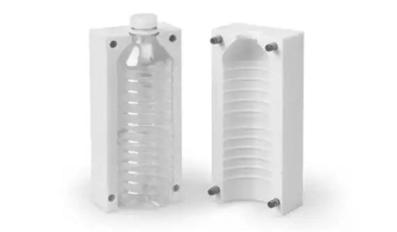
Injection molding injects molten plastic into a closed mold cavity under high pressure, producing complex, precise parts in high volume. Extrusion forces plastic through a die to create continuous profiles like pipes or sheets. Blow molding inflates a plastic tube inside a mold to create hollow objects like bottles. For aerospace, injection molding is preferred for precision components with complex geometries; extrusion suits seals and trim; blow molding is rarely used.
How to choose the right plastic material for aerospace injection molding?
Start with performance requirements: temperature range, chemical exposure, mechanical stress, and flammability. PEEK handles extreme heat and chemicals; PEI offers excellent flame resistance; PC provides impact resistance and clarity. Next, consider cost—high-performance materials are expensive, so match material to actual needs. Finally, ensure processability: some materials require specialized equipment and tight process control. Always verify compliance with aerospace standards like FAA flammability or outgassing limits.
What are the common mistakes designers make in aerospace injection molding design and how to avoid them?
Ignoring wall thickness uniformity: Uneven walls cause sink marks, voids, and warpage. Maintain consistent thickness; use smooth transitions when changes are necessary. Forgetting draft angles: Without draft, parts stick in the mold. Add 0.5°–3° draft depending on surface texture and depth. Poor rib and boss design: Ribs too thick cause sink marks; ribs too thin don’t provide strength. Keep rib thickness at 50–80% of nominal wall. Use gussets on tall bosses. Sharp corners: Stress concentrations lead to cracking. Add fillets with minimum 0.5mm radius.
What certifications should an aerospace injection molding provider have?
AS9100 is the aerospace-specific quality management standard—it’s essential. ISO 9001 is the baseline. For specialized processes, NADCAP certification may be required. Beyond certifications, look for documented material traceability, in-process monitoring, and inspection capabilities (CMM, tensile testing, etc.). Ask about their experience with aerospace programs and their willingness to provide full documentation.
Can aerospace injection molding replace metal components?
Yes, in many applications. High-performance polymers like PEEK and PEI offer strength-to-weight ratios that exceed many metals. Replacing metal with plastic can reduce weight by 30–60% , improve corrosion resistance, and simplify assembly. However, material selection is critical. Not all plastics can handle the temperatures, loads, or chemical exposure in aerospace environments. A thorough engineering analysis—including stress modeling and testing—is essential before committing to metal replacement.
Contact Yigu Technology for Custom Manufacturing
Need precision injection-molded components for aerospace applications? At Yigu Technology, we combine deep material expertise, precision tooling, and rigorous quality systems to deliver parts that meet the industry’s highest standards.
We work with high-performance materials including PEEK, PEI, PPS, and engineered nylons. Our team supports you from design through production—with full traceability and documentation. Contact us today to discuss your aerospace project and discover how we can help you achieve your performance and weight targets.