What is a CNC Machine Tool Spindle?
Definition
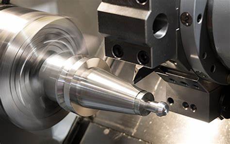
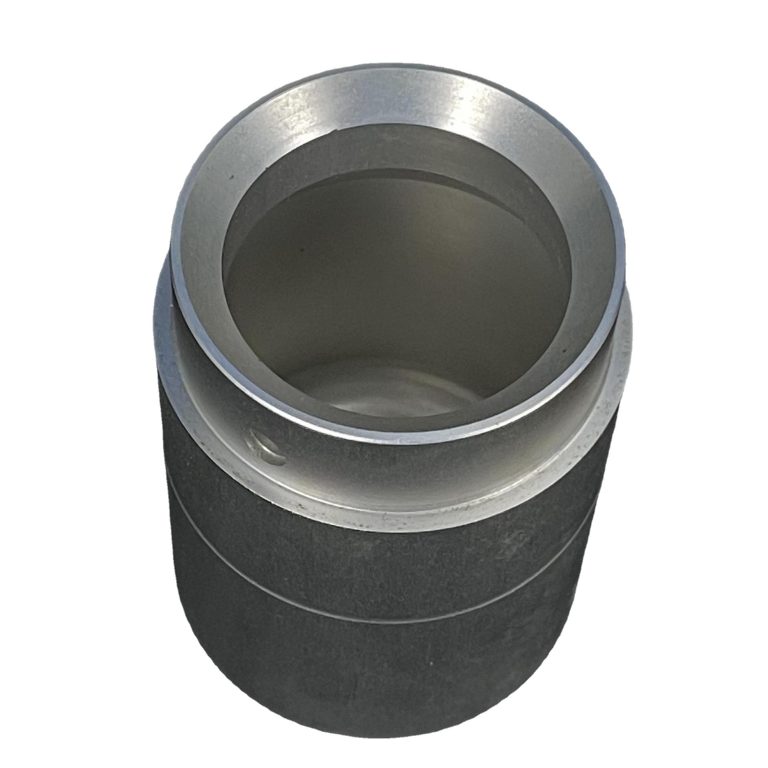
A CNC machine tool spindle is a fundamental component in a Computer Numerical Control (CNC) machining system. At its most basic, the spindle often refers to the shaft located at the center of the rotating axis of the machine tool. However, in a broader sense, the term "spindle" can also be used to describe the entire rotary unit. This comprehensive unit includes not only the shaft itself but also its bearings, which are crucial for smooth rotation, and any additional components attached to it.
The spindle plays a pivotal role in the operation of a CNC machine. It rotates on its axis, receiving input on movement from the CNC controller. This enables the spindle to precisely control the rotation speed and position, which are essential for accurate machining processes. In a CNC machining center, the spindle is a very important part, as the form of the spindle determines the speed and cutting force that the machine can achieve. A machine tool may be equipped with several spindles, with the largest one being called the main spindle. When the term "spindle" is used without further qualification, it usually implies the main spindle. There is a wide diversity of spindle configurations and options available in the market, each designed to meet the specific needs of different industries, such as metalworking, woodworking, and the manufacturing of electrical components and various CNC parts.
Structure
The structure of a CNC machine tool spindle is composed of several key elements, each contributing to its overall functionality and performance.
- Shaft: The shaft is the central component of the spindle. It is typically made of high - strength materials such as alloy steel, which provides the necessary rigidity to withstand the forces generated during machining operations. The shaft's design and manufacturing precision directly affect the spindle's rotation accuracy. For Yigu Technology example, a shaft with a high - quality surface finish and precise dimensional tolerances can minimize vibrations during rotation, resulting in better machining accuracy. In high - speed spindles, the shaft may be designed with a hollow core to reduce weight and inertia, allowing for faster acceleration and deceleration.
- Bearings: Bearings are crucial components that support the shaft and enable it to rotate smoothly. There are different types of bearings used in spindles, such as angular contact ball bearings, cylindrical roller bearings, and tapered roller bearings. Angular contact ball bearings are commonly used in high - speed spindles as they can withstand both radial and axial loads and have relatively high - speed capabilities. For instance, in a high - speed milling machine spindle, angular contact ball bearings are often arranged in a back - to - back or face - to - face configuration to provide enhanced rigidity and support for the shaft during high - speed rotation. Cylindrical roller bearings are preferred when a spindle needs to handle high radial loads, while tapered roller bearings can handle both radial and axial loads simultaneously, making them suitable for applications where the spindle is subject to complex loading conditions.
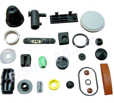
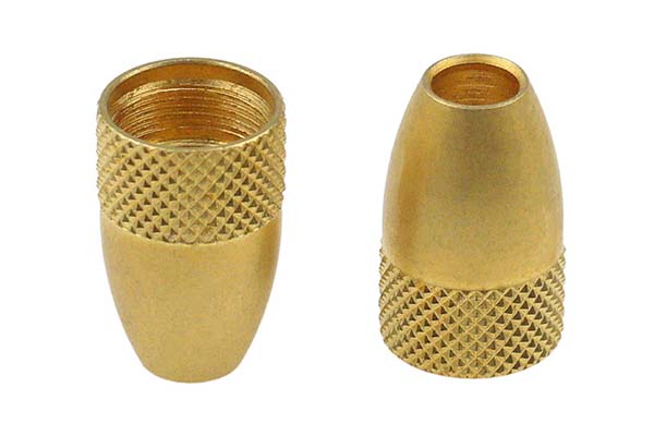
- Attached Components: There are various components attached to the spindle, depending on the specific requirements of the machining process. One of the most important attached components is the tool holder. The tool holder is used to secure the cutting tool in place on the spindle. There are different types of tool holders, such as BT (Big - Plus Taper), HSK (Hohl - Schaft - Kegel), and CAT (Conical Attachment for Tools). Each type of tool holder has its own characteristics in terms of clamping force, accuracy, and compatibility with different spindle types. For Yigu Technology example, the HSK tool holder is known for its high - precision clamping and excellent balance at high speeds, making it suitable for high - speed machining applications.
In addition to the tool holder, other components may include seals to prevent the ingress of dust, chips, and coolant into the spindle assembly, and sensors for monitoring spindle parameters such as temperature, vibration, and speed. These sensors play a vital role in ensuring the spindle's proper operation and can provide early warnings of potential problems, allowing for timely maintenance and preventing costly breakdowns.
Functions of a CNC Machine Tool Spindle
The functions of a CNC machine tool spindle are multi - faceted and crucial for the overall machining process. Each function contributes to the efficiency, accuracy, and quality of the machining operations.
Power Provision
One of the primary functions of a CNC machine tool spindle is to provide constant power within a certain speed range. This is essential to ensure sufficient cutting force during machining. When a cutting tool comes into contact with the workpiece, it needs to overcome the material's resistance to be removed. The spindle's power determines how effectively this can be achieved.
For example, in a milling operation, if the spindle cannot provide enough power, the cutting tool may struggle to cut through the material, leading to issues such as poor surface finish, tool breakage, or incomplete cuts. The power of the spindle is related to its motor and transmission system. High - power spindles are often required for machining tough materials like stainless steel or titanium. A spindle with a more powerful motor can maintain a consistent cutting force even at high - speed rotations. In a comparison of different spindle models, Spindle A with a 15 - kW motor can maintain a cutting force of 500 N within a speed range of 1000 - 8000 RPM, while Spindle B with a 10 - kW motor can only provide a maximum cutting force of 350 N within the same speed range. This shows the direct impact of spindle power on the machining process.
Positioning
Precise positioning of the spindle is another critical function. The spindle needs to be able to stop accurately at a certain position for various operations, such as tool changing, boring tool withdrawing, and special work requirements.
During tool changing, the spindle must stop at a specific angular position so that the old tool can be safely removed and a new one installed. If the positioning is inaccurate, it can lead to misalignment of the tool, which may cause problems during subsequent machining operations. For instance, in a high - precision machining center, the spindle positioning accuracy for tool changing should be within ±0.01 degrees. In boring operations, when the boring tool needs to be withdrawn from the workpiece, the spindle's accurate positioning ensures that the tool is removed smoothly without causing damage to the bore or the tool itself. This positioning function is achieved through a combination of encoder systems and servo - control technology. Encoders provide feedback on the spindle's position, and the servo - control system adjusts the spindle's movement accordingly to reach the desired position precisely.
Synchronous Operations
- Synchronous Operation with the Servo Shaft
- The spindle can operate synchronously with the servo shaft. This means that for every rotation of the spindle, the servo shaft moves a certain linear distance. This synchronization is crucial in operations such as thread cutting. In thread cutting, the relative motion between the spindle (which rotates the workpiece) and the servo - controlled feed axis (which moves the cutting tool axially) must be precisely coordinated. For Yigu Technology example, when cutting a metric M10 x 1.5 thread, the spindle must rotate at a speed such that for each full rotation, the cutting tool advances 1.5 mm along the workpiece's axis. If the synchronization is off, the resulting thread will have incorrect pitch or other defects. This synchronous operation is typically achieved through the CNC controller, which calculates and controls the speed and position of both the spindle and the servo shaft based on the programmed machining parameters.
- Synchronous Operation in Multi - Spindle Systems
- In systems with multiple spindles, two or more spindles can operate synchronously. This is beneficial in applications where multiple operations need to be performed simultaneously on the same workpiece or on multiple workpieces in a coordinated manner. For Yigu Technology example, in a multi - spindle lathe used for manufacturing complex parts, one spindle may be used for rough turning while another spindle simultaneously performs a finishing operation on the same workpiece. The synchronous operation of these spindles ensures consistent machining quality and reduces the overall machining time. In a multi - spindle milling machine, different spindles can be used to machine different features of a workpiece simultaneously, such as one spindle milling a slot while another spindle drills a hole. The synchronization of these spindles is carefully controlled by the CNC system to ensure that the operations are carried out in the correct sequence and at the right time.
Types of CNC Machine Tool Spindles
The diversity of CNC machine tool spindles caters to a wide range of machining requirements. Different types of spindles have their own unique characteristics, which are crucial for various applications in the manufacturing industry.
Classification by Taper
One common way to classify CNC machining center spindles is according to the spindle taper. In this classification, the BT (Big - Plus Taper) series is widely recognized, with common models such as BT30, BT40, BT50, and BT60. The number after BT represents the taper interface diameter of the tool holder, and these different types of spindles have distinct features and applications.
BT30 Spindle
The BT30 spindle is characterized by its relatively small diameter. This small diameter enables it to achieve a relatively high maximum speed compared to spindles with larger diameters. For example, in a high - speed milling operation for small - scale mold making, a BT30 spindle can reach speeds of up to 20,000 RPM in some advanced models. This high - speed capability makes it well - suited for applications that require high - speed rotation, such as drilling and tapping operations. In a drilling and tapping center, the BT30 spindle can quickly and accurately create holes and threads in workpieces. It is also a popular choice for small machining centers, especially those involved in mold manufacturing. The high - speed rotation of the BT30 spindle allows for precise and efficient cutting of intricate mold shapes, ensuring high - quality surface finishes and dimensional accuracy.
BT40 Spindle
The BT40 spindle has a medium - sized diameter. Its maximum speed is somewhat limited compared to the BT30 spindle, usually reaching around 12,000 - 15,000 RPM in standard configurations. However, this spindle offers a good balance between speed and torque. It can be used for both finishing and rough machining operations. In finishing operations, the BT40 spindle's relatively stable rotation at moderate speeds ensures smooth surface finishes. For example, when machining a precision - engineered part with tight tolerance requirements, the BT40 spindle can achieve the necessary accuracy. In rough machining, its sufficient torque allows it to remove large amounts of material efficiently. It is also suitable for molds with larger drilling diameters. In a mold - making process where large - diameter holes need to be drilled, the BT40 spindle can handle the task with ease, making it the spindle with the widest application range among these types.
BT50 and BT60 Spindles
BT50 and BT60 spindles are generally designed for rough machining operations. Their maximum speed is relatively low, typically only reaching 8000 RPM. These spindles are characterized by their large diameters, which contribute to their high torque capabilities. In heavy - duty machining, such as removing large amounts of material from a steel workpiece during the initial stages of manufacturing a large - scale mechanical component, the high torque of BT50 and BT60 spindles can ensure efficient material removal. However, due to their lower speed and larger size, they are not commonly used in standard CNC machining centers that require a combination of high - speed and precision operations. But in industries like large - scale metal forging and heavy - machinery manufacturing, where the focus is on heavy - duty material removal, BT50 and BT60 spindles play a vital role.
The following table summarizes the characteristics of these spindles by taper:
| Spindle Type | Taper Interface Diameter | Maximum Speed | Typical Applications |
| BT30 | Small | Up to 20,000 RPM (in some models) | Drilling, tapping, small - scale mold making in small machining centers |
| BT40 | Medium | 12,000 - 15,000 RPM | Finishing and rough machining, molds with larger drilling diameters |
| BT50 and BT60 | Large | 8000 RPM | Rough machining in heavy - duty manufacturing industries |
High - speed Spindles
High - speed spindles are essential in modern CNC machining, especially for materials that require high - speed cutting to achieve optimal results. There are two main types of high - speed spindles: integral motor spindles and belt - driven spindles.
Integral Motor Spindle
The integral motor spindle, also known as an electric spindle, has the motor integrated directly into the spindle unit. This design allows for extremely high rotational speeds, with some models capable of reaching up to 60,000 RPM. For instance, in the aerospace industry, when machining lightweight and heat - sensitive materials like titanium alloys for aircraft components, the high - speed cutting provided by an integral motor spindle can reduce heat generation during machining, minimizing the risk of material deformation. The high - speed capability also enables high - precision machining of complex geometries, such as the intricate blades of a turbine engine. However, this high - speed operation comes at the cost of a relatively limited service life. The high - speed rotation subjects the spindle components, such as bearings and the motor, to significant stress and wear. As a result, the maintenance intervals for integral motor spindles are often shorter compared to other spindle types, and the cost of replacement parts can be relatively high.
Belt - driven Spindle
Belt - driven spindles use a belt to transfer power from the motor to the spindle. They can reach a maximum speed of around 15,000 RPM. Although their speed is lower than that of integral motor spindles, belt - driven spindles offer several advantages. They can achieve greater levels of power and torque. In a woodworking application where large - diameter cutting tools are used to shape solid wood into furniture components, the high torque of a belt - driven spindle can ensure smooth and efficient cutting. The cost of a belt - driven spindle is generally lower than that of an integral motor spindle. This cost - effectiveness makes it a popular choice for applications where high - speed cutting is not the primary requirement but a balance between power, torque, and cost is needed. Additionally, the maintenance of belt - driven spindles is often more straightforward, as the belt is a relatively easy - to - replace component compared to the complex internal components of an integral motor spindle.
The comparison between integral motor spindles and belt - driven spindles is shown in the following table:
| Spindle Type | Maximum Speed | Power and Torque | Cost | Service Life and Maintenance |
| Integral Motor Spindle | Up to 60,000 RPM | High - speed operation, but relatively lower torque compared to belt - driven spindles in some cases | High | Limited service life, more frequent maintenance due to high - speed wear |
| Belt - driven Spindle | Up to 15,000 RPM | Greater power and torque levels, suitable for applications requiring more force | Low | Longer service life in normal operation, easier maintenance as the belt is easily replaceable |
How to Choose the Right CNC Machine Tool Spindle
Selecting the appropriate CNC machine tool spindle is crucial for achieving optimal machining results. A wrong choice can lead to inefficiencies, poor - quality work, and increased production costs. Here are some key factors to consider when making this important decision.
Consider the Machining Material
The type of material being machined has a significant impact on the spindle requirements. Different materials have different hardness levels, which directly affect the spindle's speed and power needs.
- Aluminum: Aluminum is a relatively soft material. For machining aluminum, high - speed spindles are often preferred. High - speed rotation can reduce the cutting force and prevent the aluminum from getting deformed or damaged during the machining process. For Yigu Technology example, an integral motor spindle with a speed of 30,000 - 60,000 RPM can be very effective for aluminum machining. This high - speed operation allows for fast material removal and can achieve excellent surface finishes. In a comparison, when machining aluminum with a spindle running at 10,000 RPM, the surface roughness was measured at 3.2μm, while with a spindle running at 30,000 RPM, the surface roughness was reduced to 1.6μm.
- Steel: Steel is much harder than aluminum. Machining steel requires more torque and power. A belt - driven spindle or a spindle with a larger diameter (such as BT50 or BT60) can be more suitable. These spindles can provide the necessary power to cut through the steel effectively. When drilling a hole in a steel workpiece, a spindle with a lower speed (around 1000 - 3000 RPM for large - diameter holes) and higher torque can ensure that the drill bit can penetrate the steel without breaking. A spindle with a torque of 50 N·m can handle the drilling operation in a 20 - mm - thick steel plate much better than a spindle with a torque of 20 N·m.
- Wood: Wood is a soft material, but it also has unique characteristics. High - speed spindles can be used for woodworking, especially for operations like carving and fine milling. However, the power requirements are generally lower compared to metal machining. A spindle with a speed of 10,000 - 15,000 RPM and a relatively lower power output (around 1 - 3 kW) can be sufficient for most woodworking tasks. For instance, when carving intricate patterns on a wooden panel, a high - speed spindle can make the cuts cleanly and precisely, enhancing the aesthetic appeal of the final product.
Match the Machining Process
The machining process, whether it is rough machining or finishing, also plays a vital role in spindle selection.
- Rough Machining: In rough machining, the goal is to remove a large amount of material quickly. This requires a spindle with high torque. Spindles with larger diameters, such as BT50 and BT60, are ideal for rough machining. These spindles can handle the high - force operations involved in removing large chunks of material. For example, in the initial stages of manufacturing a large - scale steel component, a BT50 spindle can be used to rapidly remove excess material, reducing the overall machining time. A BT50 spindle can remove material at a rate of 50 cm³/min in rough machining, while a smaller - diameter spindle like BT30 can only remove material at a rate of 15 cm³/min under the same conditions.
- Finishing: Finishing operations focus on achieving high - precision and smooth surface finishes. Spindles with high - speed capabilities and good rotation accuracy are more suitable. For example, in precision mold making, a high - speed spindle with an accuracy of ±0.001 mm can ensure that the final product has a smooth surface and tight tolerances. An integral motor spindle with a high - speed range and low vibration characteristics is often used for finishing operations. In a finishing operation of a precision - engineered part, a spindle with a vibration level of less than 0.1 g can produce a surface finish with a roughness of less than 0.8μm, which is crucial for applications where aesthetics and functionality are both important.
Evaluate Spindle Specifications
When choosing a spindle, it is essential to evaluate its key specifications.
- Speed Range: The speed range of a spindle determines the variety of machining operations it can perform. A spindle with a wide speed range offers more flexibility. For example, a spindle with a speed range of 500 - 20,000 RPM can be used for a wide range of applications, from slow - speed, high - torque operations like boring in steel to high - speed milling of aluminum. In a multi - material machining shop, such a spindle can adapt to different material requirements without the need for frequent spindle replacements.
- Power: The power of the spindle is directly related to its ability to perform work. Higher - power spindles are required for machining tough materials or for operations that involve large - scale material removal. A 15 - kW spindle can handle more demanding machining tasks compared to a 5 - kW spindle. In a comparison, when machining a large - size titanium alloy workpiece, a 15 - kW spindle can complete the machining process in 2 hours, while a 5 - kW spindle would take 5 hours, highlighting the importance of power in machining efficiency.
- Torque: Torque is the rotational force that the spindle can exert. It is especially important for operations that require a high - force application, such as threading or deep - hole drilling. Spindles with high torque are needed for machining hard materials. A spindle with a torque of 80 N·m can perform deep - hole drilling in a hardened steel workpiece more effectively than a spindle with a torque of 40 N·m. In threading operations, sufficient torque ensures that the threads are formed accurately and without any defects.
In Yigu Technology summary, choosing the right CNC machine tool spindle requires a comprehensive consideration of the machining material, the machining process, and the spindle's specifications. By carefully evaluating these factors, manufacturers can select a spindle that maximizes machining efficiency, quality, and productivity.