Introduction
If you have ever struggled to machine hard metals like titanium or Inconel, or needed to create complex shapes with tight tolerances, you are not alone. Traditional machining methods often hit limits with these challenges. The electrical discharge machining process (EDM) offers a powerful solution. It uses controlled electrical sparks to erode material—hence the name spark erosion. This guide covers everything you need to know about EDM: how it works, key parameters, material effects, process variations, electrode technology, and practical applications. Whether you run a CNC shop, work as a manufacturing engineer, or are exploring non-traditional machining, this article answers your most pressing questions.
How Does the EDM Process Work at a Basic Level?
EDM is a thermal machining process that does not rely on physical cutting tools. Instead, it uses electrical sparks to remove material.
Key Components of an EDM System
| Component | Function |
|---|---|
| Electrode | Conductive tool (graphite or copper) that delivers electrical pulses |
| Workpiece | Conductive material to be shaped (steel, aluminum, tungsten) |
| Dielectric fluid | Insulating liquid (deionized water or mineral oil) that cools, flushes debris, and initiates sparks |
| Pulse generator | Creates short, high-voltage electrical pulses |
| Servo control system | Maintains precise spark gap (0.001–0.02 mm) between electrode and workpiece |
The Spark Erosion Cycle
- The pulse generator sends an electrical charge to the electrode.
- The dielectric fluid ionizes, creating a conductive path.
- A spark jumps across the gap, reaching 8,000–12,000°C . Heat melts and vaporizes a tiny amount of workpiece material.
- The pulse ends, and dielectric fluid flushes away melted debris.
- The servo control adjusts the electrode position to maintain the ideal gap. The cycle repeats hundreds or thousands of times per second.
Real-world example: A medical device manufacturer needed tiny, intricate holes in stainless steel surgical needles. Using EDM, they achieved a hole diameter of 0.1 mm with a tolerance of ±0.005 mm —impossible with traditional drilling. The dielectric fluid (deionized water) ensured burr-free surfaces, critical for patient safety.
What Parameters Control the EDM Process?
Success depends on tuning the right parameters. Small adjustments can mean the difference between a smooth finish and a damaged workpiece.
Critical EDM Parameters
| Parameter | Definition | Impact |
|---|---|---|
| Pulse on time (Ton) | Duration of each electrical pulse (microseconds) | Longer = more material removal (higher MRR) but rougher surface |
| Pulse off time (Toff) | Time between pulses (microseconds) | Longer = less heat buildup but lower MRR |
| Current setting (Ip) | Peak current of each pulse (amps) | Higher = faster MRR but deeper heat-affected zone |
| Gap voltage (Vg) | Voltage needed to initiate a spark | Higher = larger gap (better flushing) but slower initiation |
| Polarity | Electrode positive or negative | Negative electrode = less wear; Positive = faster MRR |
| Flushing pressure | Pressure of dielectric fluid | Higher = better debris removal but may cause vibration |
Tuning Tips for Common Goals
| Goal | Settings | Example Outcome |
|---|---|---|
| Maximize MRR (roughing) | Long Ton (100–500 µs), high Ip (20–100 A), short Toff (20–50 µs) | 40% faster roughing in H13 steel mold cavity |
| Minimize surface roughness (finishing) | Short Ton (5–20 µs), low Ip (1–5 A), long Toff (50–100 µs) | Ra 0.1 µm finish on titanium watch cases |
| Balance speed and precision | Ton = 20–50 µs, Ip = 5–15 A, Toff = 30–60 µs | Automotive engine components |
Key fact: According to the Journal of Manufacturing Processes, optimizing pulse on time and flushing pressure together can reduce EDM cycle time by up to 35% while maintaining surface quality.
What Happens to Your Workpiece During EDM?
EDM leaves a mark on the workpiece. Understanding these effects is critical for applications where strength, durability, or precision is non-negotiable.
Three Surface Layers from EDM
| Layer | Thickness | Characteristics |
|---|---|---|
| Recast layer | 5–50 µm | Molten material reattached; hard but brittle; can crack under stress |
| Heat-affected zone (HAZ) | 10–100 µm | Microstructure changes due to heat; may lose hardness |
| Base material | Unaffected | Maintains original properties |
Common Material Challenges and Solutions
| Challenge | Cause | Solution |
|---|---|---|
| Micro-cracking | Thermal stress exceeds material strength (common in high-carbon steels) | Use shorter Ton, lower Ip, post-EDM stress relief annealing |
| Poor surface integrity | Roughness or burrs affecting seals or hydraulic systems | Combine finishing EDM with abrasive flow machining (AFM) |
| Debris buildup | Melted material clogs small features | Increase flushing pressure; use vacuum-assisted or dual-nozzle flushing |
Case study: A defense contractor solved micro-cracking in high-carbon steel by reducing Ip from 15 A to 8 A and adding a 2-hour annealing step at 600°C.
Expert insight: For titanium or Inconel (common in aerospace), the HAZ is particularly sensitive. Powder-mixed EDM (adding fine powder to dielectric) can reduce HAZ depth by up to 40% compared to conventional EDM.
What Are the Different EDM Techniques?
EDM is not one-size-fits-all. Specialized variations tackle specific challenges.
| Technique | How It Works | Best For | Key Benefits |
|---|---|---|---|
| Roughing EDM | High current, long pulses; fast material removal | Large parts, mold cavities, initial shaping | Fast MRR, low cost |
| Finishing EDM | Low current, short pulses; precision and smoothness | Medical parts, aerospace components | Ra 0.1–1.6 µm, minimal HAZ |
| Micro-EDM | Miniaturized electrodes, ultra-short pulses | Micro-components (sensor probes, micro-gears) | Features as small as 0.001 mm |
| Powder-mixed EDM | Fine powder (aluminum, silicon carbide) in dielectric | Improving surface finish, reducing HAZ | Smoother finish, shallower HAZ |
| Dry EDM | Gas (air, nitrogen) instead of liquid dielectric | Electronics; parts where liquid causes contamination | No fluid cleanup, eco-friendly |
| Vibration-assisted EDM | Small vibrations to electrode or workpiece | Deep slots, blind holes where debris gets trapped | Reduces short circuits, faster MRR |
Case study: A smartphone manufacturer machining tiny copper connectors for 5G antennas had 20% rejects with conventional EDM due to clogged 0.05 mm slots. Switching to vibration-assisted EDM (100 Hz vibration, 5 µm amplitude) cut rejects to 2% and increased production speed by 15% .
Adaptive Control EDM: Smart Machining
Adaptive control uses sensors to monitor real-time process data (gap voltage, current, spark frequency) and automatically adjusts parameters. For example:
- If debris clogs the gap, the system increases flushing pressure.
- If electrode wears too quickly, it adjusts polarity or current.
Real-world impact: An automotive supplier installed adaptive control EDM on their mold-making lines. They saw a 25% reduction in setup time and an 18% increase in tool life —saving over $100,000 per year in electrode costs.
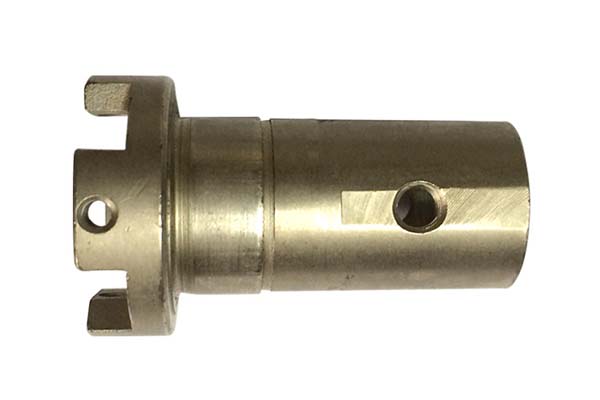
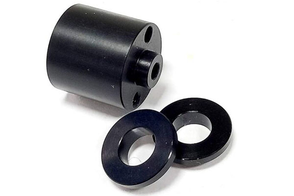
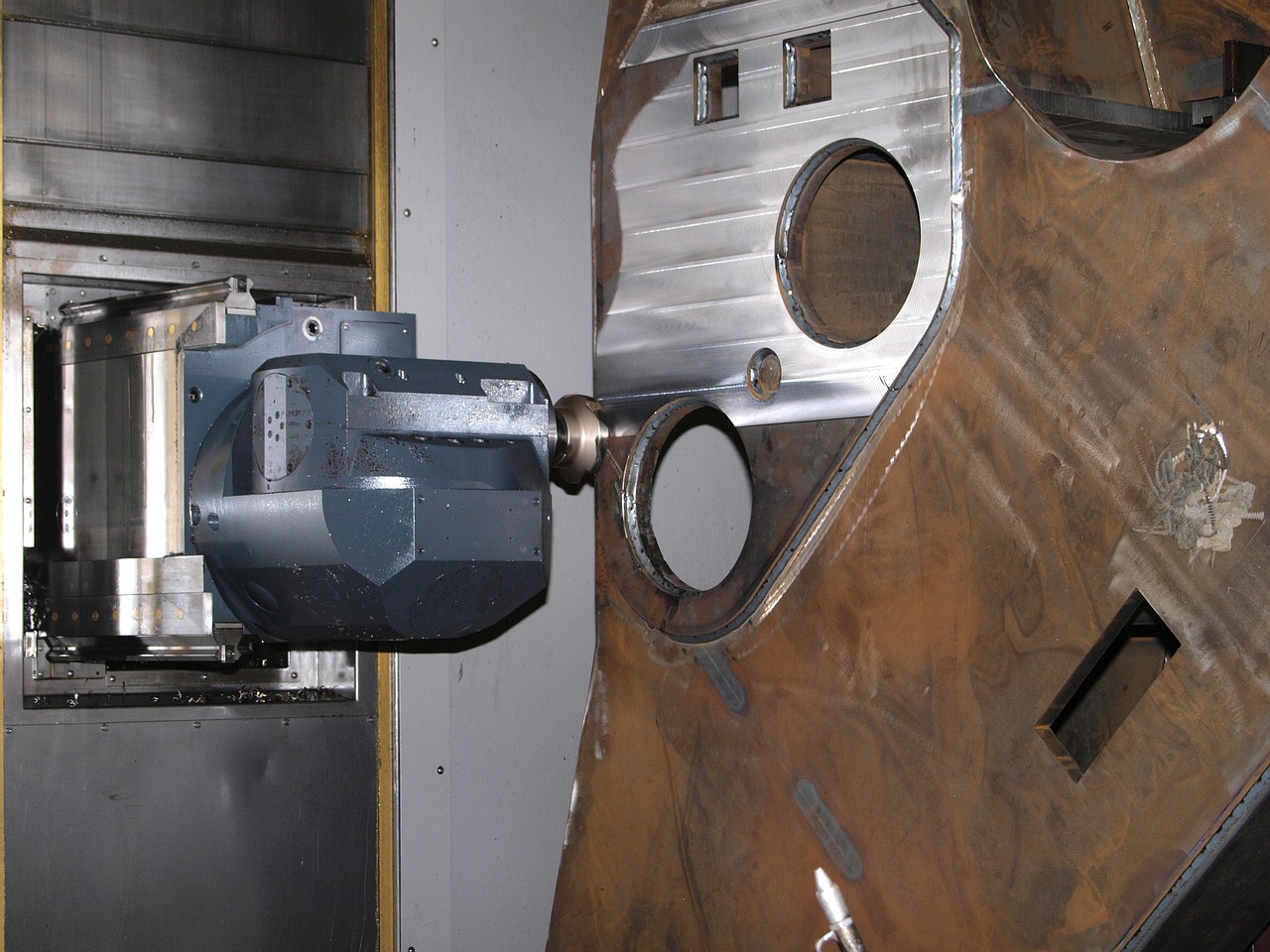
How Do You Select and Design Electrodes?
The electrode is just as important as the workpiece. Poor electrode design or material choice can ruin even the best-tuned process.
Electrode Material: Graphite vs. Copper
| Material | Pros | Cons | Best For |
|---|---|---|---|
| Graphite | Low cost, high thermal conductivity, easy to machine | Brittle, produces dust | Roughing, large electrodes, high-current applications |
| Copper | High precision, low wear, smooth surface finish | More expensive, harder to machine | Micro-EDM, finishing, tight tolerances |
Data point: According to EDM Today, graphite electrodes have 30–50% lower wear rates than copper in high-current roughing, but copper produces 20–30% smoother surface finishes in finishing.
Electrode Design Best Practices
| Practice | Why It Matters |
|---|---|
| Avoid sharp corners | Concentrate electrical energy, causing uneven wear and poor finish. Use rounded edges (minimum radius 0.1 mm). |
| Account for wear | Electrode wear is 5–15% of size. Design 10 mm slot with 9.8 mm electrode to compensate. |
| Add flushing channels | 1–2 mm diameter channels improve fluid flow; critical for deep features like blind holes. |
Example: A tool maker had uneven wear on a graphite electrode for a plastic injection mold. Adding two 1.5 mm flushing channels and rounding corners (0.05 mm to 0.2 mm radius) reduced wear by 40% and extended electrode life from 50 parts to 80 parts.
3D Electrodes and Wear Compensation
For complex parts like turbine blades or dental implants, 3D electrodes (machined from solid blocks using 5-axis CNC) allow precise shaping of undercuts and curves.
Wear compensation software tracks electrode wear during machining and adjusts position in real time. If the electrode wears 0.02 mm on one side, the software shifts it 0.02 mm to maintain dimensional accuracy.
What Is Yigu Technology’s Perspective?
At Yigu Technology, we believe the electrical discharge machining process is a cornerstone of modern precision manufacturing. As industries demand smaller, harder, and more complex components, EDM has evolved from a niche tool to a mainstream solution—thanks to advancements like adaptive control and 3D electrodes.
We often recommend powder-mixed EDM for clients prioritizing surface integrity, as it balances speed and quality better than traditional methods. We also emphasize electrode material selection: pairing graphite for roughing with copper for finishing can cut production time by 20–30% while maintaining precision. As manufacturing trends shift toward miniaturization and sustainability, we expect dry EDM and smart adaptive systems to become even more critical—helping clients reduce waste and improve efficiency.
Conclusion
The electrical discharge machining process uses controlled electrical sparks to erode material from conductive workpieces. Key components include the electrode, workpiece, dielectric fluid, pulse generator, and servo control system. Critical parameters—pulse on time, current, and flushing pressure—determine material removal rate and surface finish. EDM leaves a recast layer (5–50 µm) and heat-affected zone (10–100 µm) that may require post-processing for critical applications. Process variations include roughing, finishing, micro-EDM, powder-mixed EDM, dry EDM, and vibration-assisted EDM. Electrode material selection (graphite vs. copper) and design (avoid sharp corners, add flushing channels) significantly impact results. With tolerances as tight as ±0.001 mm and the ability to machine hardened steels, titanium, and Inconel, EDM is indispensable for aerospace, medical, automotive, and electronics manufacturing.
FAQs
Can EDM machine non-conductive materials?
No. EDM requires both the electrode and workpiece to be conductive. For non-conductive materials like ceramics or plastics, use alternative processes like laser machining.
What is the maximum material thickness EDM can handle?
EDM can machine materials up to 300 mm thick. Thicker parts require better flushing (e.g., through-hole flushing) to remove debris. For parts over 100 mm, expect longer cycle times.
How accurate is EDM?
Modern EDM machines can achieve tolerances as tight as ±0.001 mm , making them ideal for precision applications like medical devices and aerospace components.
Is EDM expensive compared to traditional machining?
EDM has higher upfront costs (machines range $50,000–$500,000 ) but lower per-part costs for complex or hard-to-machine parts. For simple parts like flat plates, traditional machining is cheaper.
How do I maintain an EDM machine?
Key maintenance steps include: changing dielectric fluid every 6–12 months, cleaning flushing nozzles weekly, calibrating the servo system monthly, and inspecting electrodes for wear before each use.
Contact Yigu Technology for Custom Manufacturing
At Yigu Technology, we integrate EDM into our precision manufacturing capabilities to deliver complex, high-accuracy components. Our sink EDM and wire EDM systems handle hardened steels, titanium, Inconel, and other difficult-to-machine materials. We combine EDM with 5-axis CNC machining and CMM inspection to achieve tolerances as tight as ±0.001 mm. Whether you need micro-features for medical devices, deep cavities for molds, or complex geometries for aerospace components, we deliver precision you can trust.
Ready to solve your toughest machining challenges with EDM? Contact Yigu Technology today for a free consultation and quote. Let us help you turn complex designs into precision-machined reality.