Introduction: Industrial Milling - The "Precision Engraver" of Modern Manufacturing
When you see the complex parts of aerospace, the core components of automobile engines, or the delicate textures of precision molds, industrial milling is behind it Technical support. As one of the core processes in metalworking, it removes materials through the rotation of the tool and the relative movement of the workpiece, accurately shaping various complex structures. However, for manufacturing practitioners, technology selectors, or industry learners, how to master the core principles of milling, choose appropriate equipment tools, and deal with the machining problems of different materials is still a problem that needs to be explored in depth. This article will comprehensively dismantle the key knowledge points of industrial milling from the basics to the actual combat to help you truly understand this core manufacturing technology.
1. Milling process basics: what makes materials "precision forming"?
To master industrial milling, we must first understand its core logic - the essence of material removal is the controllable cutting effect of tools and workpieces. In this process, several key parameters directly determine the machining effect, and we break it down one by one based on actual operation scenarios:
1. Balance of core movement and force
At the heart of milling is the alignment of spindle motion with feed motion: the spindle drives the milling cutter to rotate at high speed (typically at 1000-30000rpm), while the table or tool moves along a preset path (i.e., feed rate, in mm/min). The synergy between the two determines the cutting efficiency, for example, in aluminum machining, the feed speed can reach 500-2000mm/min, while in stainless steel, it needs to be reduced to 100-500mm/min to avoid tool overload.
At the same time, the control of cutting forces is key. Excessive cutting force can lead to workpiece deformation, tool wear, and even spindle vibration; If it is too small, it will reduce the processing efficiency. According to industry data, carbide tools typically have a cutting force between 1000-3000N when machining 45-gauge steel, which is adjusted according to the cutting depth (usually 0.1-5mm) and cutting width - for every 0.5mm increase in cutting depth, the cutting force increases by about 15%-20%.
2. CNC Programming: The "Command System" of Milling
Modern industrial milling relies on the foundation of CNC programming, and coordinate systems (G-code) are the core language of programming. For example, G01 command controls linear feeding, G02/G03 controls arc cutting, and G54-G59 sets the workpiece coordinate system. For example, when machining a groove with a diameter of 50mm and a depth of 10mm, the programming needs to first locate the origin of the workpiece through the G54, then use the G01 with the F-number (feed speed) to set the cutting path, and control the rotation speed of the tool through the S-value (spindle speed).
Here's a practical experience: For complex surface machining, it is recommended to use CAM software (such as Mastercam, UG) to automatically generate G-code, and then manually optimize the feed rate of the critical path - for example, reducing the feed rate by 20%-30% at the corners of the surface can effectively reduce vibration and improve surface quality.
2. Milling machine selection guide: Which equipment should be chosen in different scenarios?
There are many types of equipment for industrial milling, and the selection needs to be based on machining needs, workpiece size and precision requirements. Here's a core comparison of common milling machines:
| Milling machine type | Core features: | Applicable scenarios | Accuracy range | Typical case |
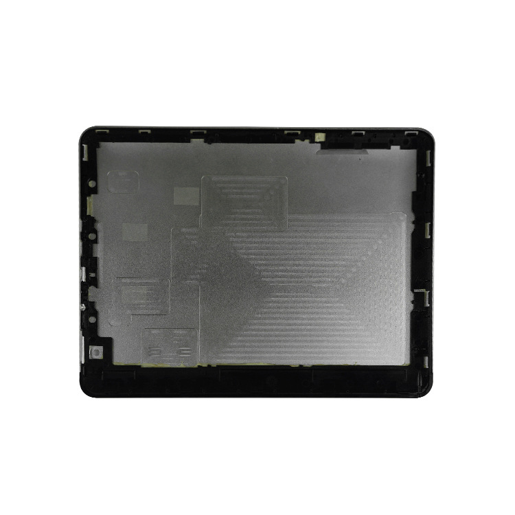
| CNC milling machine | High degree of automation, programming control, multi-axis linkage | Small and medium-sized precision machining, complex parts | ±0.005-±0.02mm | Mobile phone middle frame processing, precision gear |
| Horizontal milling machine | The spindle is horizontally arranged and rigid, making it suitable for heavy cutting | Large workpieces, deep cavity machining | ±0.01-±0.03mm | Machine tool bed processing, engine block |
| Vertical milling machine | The spindle is vertically laid out, easy to operate, and the cost is moderate | Simple parts processing, single piece small batch production | ±0.015-±0.04mm | Bracket parts, simple groove processing |
| Gantry milling machine | Gantry structure, large stroke, good stability | Processing of large workpieces and plates | ±0.02-±0.05mm | Machine tool beams, large mold bases |
| Machining centers | Integrated milling, drilling, boring functions, automatic tool change | One-stop processing and mass production of complex parts | ±0.003-±0.015mm | Aerospace components, automotive gearboxes |
| Multi-axis milling (4-axis / 5-axis) | Multi-directional cutting without multiple clamping | Processing of complex curved surfaces and special-shaped parts | ±0.002-±0.01mm | Impeller and turbine blade processing |
| High-speed milling machine | The spindle speed > 15000rpm and high cutting efficiency | Soft materials and thin-walled parts processing | ±0.005-±0.01mm | Aluminum alloy shell, plastic mold |
| Precision milling machines | High rigidity spindle, constant temperature control, error compensation | Ultra-high precision parts processing | ±0.001-±0.005mm | Optical instrument parts, micro gears |
Practical suggestions: If it is small and medium-sized production and complex structures need to be processed, give priority to the machining center, which can reduce the number of clamping times and improve efficiency; If it is a large workpiece (such as a length of > 2 meters), a gantry milling machine must be chosen, and its gantry structure can ensure the stability of processing; For aerospace profiled parts (such as blades), 5-axis milling is the only option to avoid tool interference and ensure machining accuracy.
3. Tools and cutting technology: How to make milling more efficient and durable?
The tool is the "tooth" of milling, while the cutting technique is the "bite method", which directly determines the quality and cost of machining.
1. Selection of milling cutter type and material
Common types of milling cutters include end mills, end mills, ball nose mills, slot mills, etc., and different types correspond to different machining scenarios: end mills are suitable for side cutting and groove machining, ball nose mills are suitable for curved surface finishing, and slot mills are specifically used for grooving.
In terms of material, carbide tools are currently the mainstream of industrial milling, with a hardness of more than HRC90 and wear resistance 5-10 times that of high-speed steel tools. The application of coating technology further improves the tool performance - TiN coating (titanium nitride) can improve hardness and lubricity, suitable for steel processing; AlTiN coating (aluminum titanium nitride) has strong high temperature resistance and is suitable for high-speed cutting; DLC coatings (diamond-like) are suitable for processing viscous materials such as aluminum alloys, which can effectively reduce the build-up of edges.
2. Cutting assistance technology and parameter optimization
- Coolant system: divided into oil-based and water-based coolant, oil-based coolant has good lubricity and is suitable for heavy cutting; Water-based coolant has good cooling effect and is suitable for high-speed cutting. In stainless steel machining, the use of emulsions (water-based) can reduce cutting temperatures by 30%-40% and extend tool life by more than 2 times.
- Tool Life: The core factors affecting tool life are cutting temperature, cutting force, and material viscosity. For example, due to the poor thermal conductivity of titanium alloys (only 1/5 of steel), the cutting temperature is easy to be too high, so it is recommended to use low cutting speed (50-100m/min), large feed rate (0.1-0.2mm/tooth), and AlTiN coated tools to extend the tool life from 30 minutes to 1.5 hours.
- Cutting parameter optimization: Follow the principle of "high speed low load" or "low speed high load". For soft materials (such as aluminum alloys), high speed (20000-30000rpm) and small cutting depth (0.1-0.5mm) are used for higher efficiency; for hard materials (such as hardened steel HRC55+), low speed (1000-3000rpm) and large cutting depth (1-3mm) are used to reduce tool impact.
- Chip breaking treatment: Chip breaking is achieved through tool groove design (e.g., spiral groove, corrugated groove) and adjusting the feed rate. For example, when processing mild steel, a milling cutter with a large feed rate (0.2-0.3mm/tooth) and a helix angle of 30° can make the chips break naturally and avoid entanglement of the tool.
- Dry milling: No coolant required, environmentally friendly and cost-reducing, suitable for machining cast iron, aluminum alloys and other materials. However, it should be noted that dry milling requires a cutting speed of 10%-20% lower than wet milling, and the tool needs to have better high temperature resistance (e.g. with SiAlON ceramic tools).
4. Materials and processing applications: How to "prescribe the right medicine" for different materials?
The processing objects of industrial milling cover a variety of materials such as metals and composite materials, and the physical properties of different materials vary greatly, and the processing process also needs to be adjusted accordingly.
1. Milling tips for common metal materials
| Material type | Processing difficulties | Recommended knives | Core parameters | Use Cases: |
| Aluminum alloy | It is sticky and easy to produce edges | Carbide + DLC coating | Rotation speed 10000-30000rpm, feed speed 500-2000mm/min | Automobile engine blocks, mobile phone housings |
| Stainless steel | High hardness and poor thermal conductivity | Carbide + AlTiN coating | Rotation speed 1000-5000rpm, feed speed 100-500mm/min | Medical equipment and chemical equipment parts |
| Titanium alloy | High strength and high cutting temperature | Carbide + TiSiN coating | Rotation speed 500-1500rpm, feed speed 50-200mm/min | Aerospace engine blades, orthopedic implants |
| 45 gauge steel | Highly versatile and easy to process | Carbide or high-speed steel | Rotation speed 3000-8000rpm, feed speed 300-1000mm/min | Mechanical parts, mold base |
2. Special materials and industry applications
- Composite materials (such as carbon fiber reinforced resins): The difficulty in processing is that the fibers are easy to break and the resin is easy to melt. It is recommended to use diamond-coated tools, low speed (5000-10000rpm), high feed (300-800mm/min), and use compressed air for cooling to avoid coolant corroding materials. It is used in UAV fuselage and aerospace structural parts.
- Mold manufacturing: Milling is the core process of mold processing, requiring both precision and surface quality. For cavity machining of injection molds, 5-axis milling + ball head milling cutter finishing is used to achieve surface roughness of Ra0.1-0.3μm without subsequent polishing.
- Auto parts: Milling engine crankshafts, gearbox gears and other parts need to meet the requirements of large quantities and high precision. The use of machining center + special fixture, with high-pressure cooling system, can achieve a production efficiency of 50-100 pieces per hour, and the tolerance is controlled within ±0.01mm.
- Aerospace components: aircraft landing gear, wing structural parts, etc., mostly made of titanium alloy and high-strength steel. Multi-axis milling equipment is required, with integral carbide tools, to reduce cutting forces through layered cutting to ensure the strength and accuracy of parts.
5. Precision and Quality Control: How to Maintain the "Lifeline" of Milling Machining?
In industrial manufacturing, precision is the core of product competitiveness, and the precision control of milling involves multiple links.
1. Key accuracy indicators and control methods
- Tolerance control: Choose the appropriate tolerance level according to the product requirements, with tolerances of ±0.05-±0.1mm for ordinary parts and ±0.005-±0.01mm for precision parts. Control methods include: the use of high-precision machine tools (e.g. spindle runout ≤0.002mm), optimization of clamping methods (using hydraulic clamps to reduce deformation), and regular calibration of equipment.
- Surface Roughness: Influencing factors include tool edge quality, cutting parameters, and coolant usage. For example, the use of a sharp ball nose milling cutter (cutting edge radius ≤ 0.01 mm), combined with a small cutting depth (0.05-0.1 mm) and high feed rate, can achieve a surface roughness of Ra≤0.2 μm.
- Dimensional accuracy: Real-time monitoring of machining dimensions through online inspection, such as installing contact probes on machining centers, automatically detecting key dimensions after each process, and automatically adjusting tool compensation when deviations exceed thresholds. After adopting this method, the dimensional pass rate of an auto parts factory increased from 95% to 99.5%.
2. Common problems and solutions
- Vibration Control: Vibration can lead to surface ripples and increased tool wear. Solution: Increasing machine rigidity (e.g. cast iron bed selection), optimizing cutting parameters (reducing cutting speed, increasing feed), using damping tools.
- Thermal Deformation Compensation: The heat generated during milling can cause deformation of the workpiece and the machine. Control method: Constant temperature workshop (temperature fluctuation ≤±2°C), use coolant to reduce the temperature, and add thermal deformation compensation coefficient (usually 0.001-0.003mm/°C) to the programming.
- Process monitoring: Real-time monitoring of cutting forces, spindle temperature, and tool wear through sensors. When the cutting force suddenly rises by more than 20%, it may be due to tool wear or loose workpiece clamping, and the system can automatically stop and alarm to avoid scrap generation.
- Quality control standards: Following the ISO 9001 quality management system, key parts need to be factory tested by coordinate measuring instruments, roughness meters and other equipment. The aerospace sector also needs to comply with AS9100 standards, documenting and tracing every step of the machining process.
6. Yigu Technology's viewpoint:
As an enterprise deeply involved in the field of manufacturing technology, Yigu Technology believes that industrial milling is developing in the direction of "high precision, high efficiency, and green". On the one hand, 5-axis milling and high-speed milling technologies will be further popularized, and intelligent programming and adaptive cutting combined with AI algorithms will greatly improve machining efficiency. On the other hand, dry milling, minimal lubrication technology (MQL) will be an important choice in the environmental trend.
For manufacturing practitioners, we recommend: 1) give priority to the rigidity and precision reserve of equipment when selecting to avoid equipment obsolescence due to capacity upgrades; 2) Tool investment should not be stingy, although the cost of high-quality coated tools is high, it can reduce the comprehensive processing cost (such as tool replacement time, scrap rate); 3) Pay attention to talent training, master CNC programming, equipment debugging and quality control compound talents are the core competitiveness of enterprises. In the future, only by deeply integrating technology, equipment and talents can we truly give full play to the value of industrial milling and empower product innovation.
7. FAQ:
- Q: What is the core difference between a CNC milling machine and a machining center?
A: The core difference is that the machining center has automatic tool change function and tool magazine (can accommodate 10-100 tools), which can complete multiple processes such as milling, drilling, and boring in one stop; CNC milling machines usually require manual tool changes, which is suitable for single-process processing.
- Q: What should I do if the tool is prone to wear when machining stainless steel?
A: It is recommended to choose carbide tools with AlTiN coating to reduce the cutting speed (1000-3000rpm), increase the feed, and use high-pressure emulsion cooling to avoid tool wear caused by excessive cutting temperature.
- Q: How can I improve the surface roughness of milling operations?
A: You can start from three aspects: 1) Choose sharp finishing tools (such as ball head milling cutters, diamond coated tools); 2) Optimize cutting parameters (small cutting depth, high feed rate); 3) Ensure that the coolant is fully lubricated to reduce the friction between the tool and the workpiece.
- Q: What types of parts is multi-axis milling suitable for?
A: It is suitable for the processing of complex curved surfaces, special-shaped parts, and deep-cavity parts, such as impellers, turbine blades, aerospace structural parts, etc., which can reduce the number of clamping, avoid tool interference, and improve machining accuracy and efficiency.
- Q: How to choose between dry milling and wet milling?
A: Dry milling is suitable for machining cast iron, aluminum alloy and other materials, which is environmentally friendly and reduces costs, but you need to pay attention to the high temperature resistance of the tool. Wet milling is suitable for machining difficult materials such as stainless steel and titanium alloy, with good cooling and lubrication effects, which can extend the tool life.