Introduction
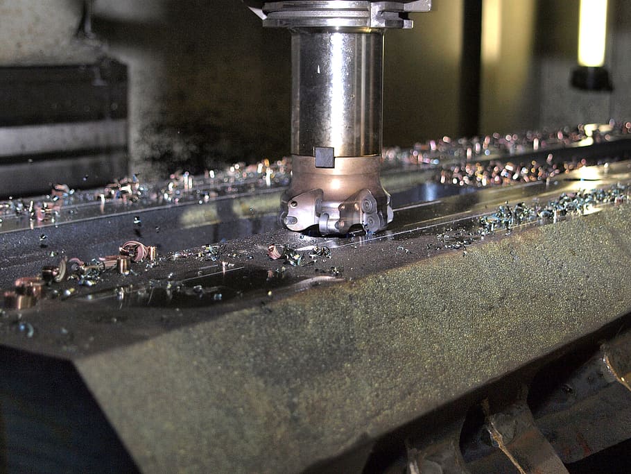
Milling is one of the most widely used machining processes in manufacturing. Industry data shows that approximately 35% of all machined parts globally are shaped through milling operations. From aerospace turbine blades to automotive engine blocks, milling accuracy directly determines product performance and service life. For example, a 0.01 mm increase in flatness error during engine block milling can reduce sealing performance by more than 15% .
At the heart of successful milling lies a critical parameter: cutting speed. It directly affects machining efficiency, tool life, and final part quality. Set it too low, and you risk poor surface finish and built-up edge. Set it too high, and rapid tool wear or even chipping increases production costs.
This guide provides a clear, practical approach to milling cutting speed calculation. We will cover basic concepts, formulas, example calculations, and how to use cutting speed calculators effectively. Whether you are a seasoned machinist or new to the trade, you will learn to set parameters with confidence.
What Is Cutting Speed and Why Does It Matter?
Definition of Cutting Speed
Cutting speed is the linear speed of a point on the cutting edge relative to the workpiece surface. It is not the same as spindle speed (RPM). Spindle speed is rotations per minute; cutting speed is the distance traveled per minute at the cutting edge.
The relationship between cutting speed and spindle speed depends on tool diameter. A larger tool requires lower RPM to achieve the same cutting speed. This relationship is the foundation of all cutting speed calculations.
Units of Cutting Speed
Two common units are used in industry:
- Metric: meters per minute (m/min)
- Imperial: surface feet per minute (SFM)
The conversion is: 1 SFM ≈ 0.3048 m/min. Most domestic machining uses metric, while North American operations often use SFM. When working with international specifications, quick unit conversion is essential.
Factors Affecting Cutting Speed
Cutting speed is not fixed—it must be adjusted based on multiple factors.
| Factor | Effect on Cutting Speed | Adjustment Guidelines |
|---|---|---|
| Workpiece Material | Harder, tougher materials generate more heat and wear | Hard steel: reduce speed 30–50% vs. aluminum |
| Tool Material | Higher heat resistance enables higher speeds | Carbide: 2–3× higher speed than HSS |
| Machining Accuracy | Finishing requires lower cutting forces | Finishing: 10–20% higher speed than roughing, but lower feed |
| Machine Rigidity | Poor rigidity causes vibration | Older machines: reduce speed 15–20% to avoid chatter |
Understanding these factors allows you to adjust calculated speeds to real-world conditions.
What Is the Cutting Speed Calculation Formula?
The Core Formula
The fundamental formula for cutting speed in milling is:
Metric: Vc = (π × D × N) / 1000
Imperial: SFM = (π × D × N) / 12
Where:
- Vc = cutting speed (m/min)
- SFM = cutting speed (surface feet per minute)
- π = 3.1416
- D = milling cutter diameter (mm for metric; inches for imperial)
- N = spindle speed (RPM)
This formula derives from the circumference of the tool. Each revolution moves the cutting edge a distance of π × D. Multiply by rotations per minute to get distance per minute, then convert units.
Variable Definitions and Units
To avoid calculation errors, ensure consistent units:
- Diameter (D) : Millimeters for metric calculations; inches for imperial
- Spindle Speed (N) : Revolutions per minute (RPM) for both systems
- Cutting Speed Result: m/min for metric; SFM for imperial
If you mix units—millimeters with SFM—the result will be incorrect. Always verify unit consistency before calculating.
Example Calculation
Scenario: A shop uses a 10 mm carbide end mill to machine 45 steel. Spindle speed is set to 2000 RPM. Calculate cutting speed.
Metric formula: Vc = (3.1416 × 10 × 2000) / 1000 = 62.83 m/min
For 45 steel with carbide tools, the recommended cutting speed range is 60–80 m/min. This result falls within the range, confirming appropriate parameters.
What if speed changes?
- At 2500 RPM: Vc = 78.54 m/min—still within range
- At 3000 RPM: Vc = 94.25 m/min—exceeds range, accelerating tool wear
This demonstrates how cutting speed changes with spindle speed and why staying within recommended ranges matters.
How Do You Use a Cutting Speed Calculator?
Features and Benefits
A cutting speed calculator milling tool simplifies parameter selection. Core functions include:
- Cutting speed calculation from diameter and RPM
- Reverse calculation—determine required RPM from target cutting speed
- Automatic unit conversion between metric and imperial
Compared to manual calculation, calculators offer three advantages:
- Accuracy: Eliminates human error in π values and unit conversion
- Efficiency: Instant results; quick metric/imperial switching
- Practicality: Some calculators include material-tool parameter ranges to validate results
Step-by-Step Usage
Using a cutting speed calculator requires only three steps:
- Select calculation type: Choose “calculate cutting speed” (from diameter and RPM) or “calculate spindle speed” (from cutting speed and diameter)
- Input parameters: For cutting speed calculation, enter tool diameter and spindle speed. Select units (mm or inches; RPM)
- View result: Calculator displays cutting speed. Some tools also show recommended ranges based on material and tool type
Tip: Always verify unit consistency. When diameter is in mm, result is m/min; when in inches, result is SFM. Mixing units causes errors.
Common Issues and Solutions
| Problem | Cause | Solution |
|---|---|---|
| Results don’t match actual machining | Calculator doesn’t account for material/tool factors | Use calculator with built-in material-tool database; adjust results using factor table |
| Unit conversion error | Input units don’t match selected calculation | Confirm diameter unit matches target cutting speed unit; use unit conversion function |
| Abnormal results | Parameters outside calculator range; non-numeric input | Verify parameter reasonableness (e.g., diameter 1–50 mm typical); check for numeric inputs |
How Do You Apply Cutting Speed in Practice?
Roughing vs. Finishing
Cutting speed requirements differ between roughing and finishing operations:
- Roughing: Lower speeds with higher feeds and depths of cut. Focus is on material removal rate, not surface finish.
- Finishing: Slightly higher speeds (10–20% increase) with lower feeds and depths of cut. Focus is on surface quality and dimensional accuracy.
For example, roughing 45 steel might use 60 m/min at 0.2 mm/tooth feed. Finishing the same material might use 70–80 m/min at 0.05–0.1 mm/tooth feed.
Tool Material Selection
Tool material directly determines achievable cutting speed:
- High-speed steel (HSS) : Lower speeds—30–60 m/min for steel; 100–200 m/min for aluminum
- Carbide: 2–3× higher speeds—80–150 m/min for steel; 200–500 m/min for aluminum
- Coated carbide (TiAlN, AlTiN): 10–20% higher than uncoated carbide, with extended tool life
Machine Rigidity Considerations
Machine rigidity affects how well theoretical cutting speeds translate to actual performance:
- Rigid, modern CNC machines: Can run at optimal speeds with minimal vibration
- Older or less rigid machines: May require 15–20% speed reduction to avoid chatter
When setting up a new job, start at the lower end of recommended speed range and increase gradually while monitoring tool wear and surface finish.
What Are Common Cutting Speed Ranges for Different Materials?
The following table provides recommended cutting speed ranges for common materials using carbide tools. Adjust downward for HSS; adjust upward for coated carbide.
| Material | Cutting Speed Range (m/min) | Cutting Speed Range (SFM) |
|---|---|---|
| Aluminum (6061) | 200–500 | 650–1650 |
| Mild Steel (1018) | 80–120 | 260–400 |
| 45 Steel (1045) | 60–80 | 200–260 |
| Stainless Steel (304) | 50–80 | 165–260 |
| Titanium (Grade 5) | 20–40 | 65–130 |
| Cast Iron | 70–100 | 230–330 |
| Nickel Alloys (Inconel) | 15–30 | 50–100 |
These ranges are starting points. Fine-tune based on specific tool geometry, machine condition, and desired surface finish.
How Does Cutting Speed Impact Machining Outcomes?
Tool Life
Cutting speed has an exponential effect on tool life. Doubling cutting speed can reduce tool life by 80–90% . This relationship is described by the Taylor tool life equation: V × T^n = C, where small increases in speed cause large decreases in tool life.
For production runs, optimizing cutting speed balances tool life against cycle time. Lower speeds extend tool life but increase machining time. Higher speeds reduce cycle time but increase tooling costs.
Surface Finish
Cutting speed affects surface finish through chip formation and cutting forces:
- Too low: Built-up edge forms, causing rough surface and poor finish
- Optimal: Clean cutting, smooth surface
- Too high: Heat buildup causes thermal damage; potential material smearing
For finishing passes, selecting the correct cutting speed is as important as feed rate and depth of cut.
Heat Generation
Excessive cutting speed generates heat faster than coolant can remove it. For materials with low thermal conductivity—titanium, stainless steel—this is particularly problematic. Heat concentrates at the cutting edge, accelerating tool wear and potentially causing workpiece thermal distortion.
How Is Cutting Speed Evolving with Industry Trends?
Integration with Automation
As manufacturing moves toward Industry 4.0, cutting speed calculation is integrating with machine control systems. Adaptive machining uses real-time sensors to monitor cutting forces and temperature, automatically adjusting speeds to maintain optimal conditions.
Practitioners who master manual calculation and calculator use today will be better prepared for these automated systems tomorrow.
Sustainability Considerations
Reasonable cutting speed reduces energy consumption and tool waste. Cutting at optimal speeds—not maximum speeds—extends tool life, reducing the number of tools consumed. Lower energy consumption per part supports green manufacturing initiatives.
Conclusion
Cutting speed calculation is a fundamental skill for milling practitioners. It directly determines machining efficiency, tool costs, and product quality. Reasonable cutting speed maximizes tool life while ensuring part accuracy; incorrect speed leads to frequent tool changes, increased scrap rates, and higher production costs.
The core formula—Vc = (π × D × N) / 1000—is simple, but applying it correctly requires understanding influencing factors: workpiece material, tool material, machining accuracy, and machine rigidity. Cutting speed calculators simplify the process, providing instant results and helping validate parameter choices.
As Industry 4.0 advances, cutting speed control will integrate with automated machining systems. The ability to calculate and optimize cutting speed remains essential—it is the foundation for adapting to smarter, more efficient manufacturing.
FAQ
What parameters must be entered when using a cutting speed calculator?
Core parameters are milling cutter diameter (D) and spindle speed (N). For reverse calculation—determining required RPM from target cutting speed—enter cutting speed (Vc/SFM) and diameter. Professional calculators may also request workpiece material and tool type to provide recommended range references.
Why is there a big difference in cutting speed between aluminum alloy and stainless steel?
Aluminum has low hardness, good thermal conductivity, and generates less cutting heat, allowing higher speeds (150–300 m/min). Stainless steel has higher hardness, stronger toughness, and poor thermal conductivity—cutting heat concentrates at the tool edge, requiring lower speeds (50–80 m/min) to prevent rapid wear.
Is there significant error in manual cutting speed calculation compared to using a calculator?
Error mainly comes from π approximation and unit conversion. Manual calculations often use π = 3.14, while calculators use 3.1416 or higher. Calculators also automate unit conversion. Manual error is typically 1–3%, acceptable for simple scenarios. For high-precision machining, calculators ensure accuracy.
Is the cutting speed calculation formula the same for different milling cutter types?
The core formula—Vc = (π × D × N) / 1000—is the same for all cutter types. However, for ball nose end mills, the effective cutting diameter is less than actual diameter when cutting depth is less than tool radius. For accurate control, adjust based on effective diameter. End mills use actual diameter directly.
Contact Yigu Technology for Custom Manufacturing
Need precision milled components with optimized cutting parameters? Yigu Technology combines advanced CNC machining with deep expertise in cutting speed optimization to deliver high-quality parts efficiently. Our engineers select the right tools, speeds, and feeds for your materials and applications. Contact us today to discuss your requirements.