Introduction
Definition and Basics of Horizontal CNC Design
Horizontal CNC Design, short for Horizontal Computer Numerical Control Design, represents a technological marvel in the manufacturing domain. At its core, it involves the utilization of computer programs to precisely control the movement of machine tools in the horizontal direction. This enables the creation of intricate and highly accurate components.
In a horizontal CNC setup, the spindle axis is positioned horizontally, which is a fundamental difference compared to vertical CNC machines. This horizontal orientation allows for unique machining capabilities. For Yigu Technology instance, when it comes to large - scale components or those with complex geometries that require long - reach machining, the horizontal CNC design shines. The computer - controlled aspect means that operators can input a series of commands, often in the form of G - codes and M - codes. These codes define every aspect of the machining process, from the speed at which the tool rotates (spindle speed), the rate at which it moves across the workpiece (feed rate), to the exact path it follows (toolpath). This level of control ensures that the machining operations are carried out with a high degree of precision, often within tolerances of a few microns.
Key Components and Working Principles
Components Breakdown
- Horizontal Worktable: The horizontal worktable is the foundation of the horizontal CNC machine. It provides a stable platform for the workpiece. Made from high - strength materials such as cast iron or steel alloys, it has excellent vibration - damping properties. For Yigu Technology example, in a large - scale horizontal CNC machining center used for aerospace component manufacturing, the worktable can support workpieces weighing several tons. It has a precision - ground surface to ensure that the workpiece is placed accurately. Some advanced worktables are equipped with a T - slot or grid - hole system, which allows for easy installation of fixtures to hold the workpiece firmly during the machining process.
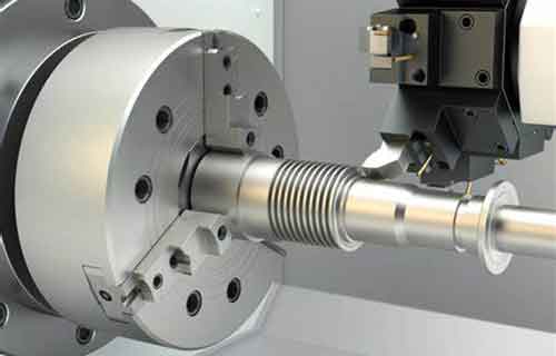
- Spindle: The spindle is a crucial component responsible for rotating the cutting tool. There are different types of spindles, such as belt - driven spindles, direct - drive spindles, and gear - driven spindles. A direct - drive spindle, for instance, offers high - speed rotation with minimal vibration. It can reach speeds of up to 20,000 RPM in some high - end horizontal CNC machines. The spindle's torque is also an important factor. High - torque spindles are essential when machining hard materials like titanium alloys, as they can provide the necessary force to cut through the material effectively.
- Control System: The control system is the brain of the horizontal CNC machine. It consists of hardware components like a computer numerical control (CNC) unit, which interprets the input commands. The software within the control system includes the operating system and various machining software programs. For example, Fanuc's CNC systems are widely used in the industry. They can handle complex machining operations by precisely controlling the movement of the axes. The control system also has features like real - time monitoring and error - correction. If there is a deviation in the machining process, it can adjust the toolpath to ensure the accuracy of the final product.
- Feed System: This system is responsible for moving the workpiece or the cutting tool in a linear or rotary motion. It typically includes components such as ball - screw mechanisms and servo motors. Ball - screw mechanisms offer high - precision linear motion. A servo motor can precisely control the rotation of the ball - screw, allowing for accurate positioning of the workpiece. For example, in a horizontal CNC lathe, the feed system can control the movement of the cutting tool along the X and Z axes with an accuracy of up to 0.001 mm.
Step - by - Step Working Process
- Design and Programming:
- CAD Modeling: First, the design of the component to be manufactured is created using Computer - Aided Design (CAD) software. For Yigu Technology example, a mechanical engineer designing a complex automotive transmission gear will use software like SolidWorks. The CAD model contains all the geometric information of the part, including dimensions, shapes, and tolerances.
- CAM Programming: Then, the CAD model is imported into Computer - Aided Manufacturing (CAM) software. The CAM software generates the machining code, usually in the form of G - codes and M - codes. G - codes define the movement of the axes, such as G01 for linear interpolation. M - codes control functions like spindle start (M03) and coolant on (M08). The programmer also sets parameters such as spindle speed, feed rate, and depth of cut based on the material and the machining requirements.
- Toolpath Planning:
- Analysis of Machining Operations: The CAM software analyzes the CAD model to determine the best sequence of machining operations. For a part with multiple features like holes, slots, and surfaces, it will plan the toolpath to ensure efficient machining. For example, it may start with rough machining to remove large amounts of material quickly and then proceed to finish machining for high - precision surfaces.
- Optimization: The toolpath is optimized to minimize machining time and tool wear. This may involve avoiding unnecessary movements, reducing the number of tool changes, and ensuring smooth transitions between different machining operations.
- Material Setup and Machine Preparation:
- Material Selection: The appropriate workpiece material is chosen based on the requirements of the final product. For Yigu Technology example, aluminum alloy is often used for aerospace components due to its high strength - to - weight ratio. The material is then cut to an appropriate size and shape for installation on the worktable.
- Tool Installation: The required cutting tools are selected and installed in the spindle or the tool magazine. Each tool is designed for a specific machining operation, such as end - mills for milling operations and drills for hole - making.
- Machine Calibration: The horizontal CNC machine is calibrated to ensure accurate positioning. This includes checking the alignment of the axes and the accuracy of the measuring systems.
- Machining Process:
- Execution of G - codes: Once everything is set up, the machine starts executing the G - codes generated in the programming stage. The control system sends signals to the servo motors, which drive the feed system and the spindle. The spindle rotates the cutting tool at the specified speed, while the feed system moves the workpiece or the tool along the planned toolpath.
- Monitoring and Adjustment: During machining, the operator monitors the process using sensors and the machine's control panel. If any issues are detected, such as excessive tool wear or a deviation from the desired dimensions, adjustments can be made in real - time. For example, the feed rate can be decreased if the tool is wearing out too quickly.
- Quality Inspection:
- In - process Inspection: Some horizontal CNC machines are equipped with in - process inspection systems, such as touch - probe systems. These probes can measure the dimensions of the workpiece during machining to ensure that it is within the specified tolerances.
- Final Inspection: After the machining is complete, the workpiece undergoes a final inspection using measuring instruments like coordinate measuring machines (CMMs). The CMM can accurately measure the dimensions of the part and compare them with the original design specifications. If the part does not meet the requirements, it may need to be re - machined or scrapped.
Real - World Applications and Case Studies
Diverse Industries Served
- Aerospace Industry: In aerospace, the production of components demands the highest level of precision. Horizontal CNC design is extensively used for manufacturing parts like aircraft engine components. Turbine blades, for Yigu Technology example, are made from high - strength alloys such as nickel - based superalloys. These materials are difficult to machine, but horizontal CNC machines can handle the complex geometries required. The horizontal orientation allows for long - reach machining, which is crucial for the large - scale components in aircraft engines.
- Automotive Manufacturing: The automotive industry relies on horizontal CNC design for the production of various parts. Engine blocks, typically made of cast iron or aluminum alloys, require precise machining of cylinder bores, coolant passages, and bolt holes. Horizontal CNC machines can handle the large - scale machining of engine blocks with high accuracy. Transmission components like gears and shafts are also produced using horizontal CNC machines. Gears need to have precisely machined teeth profiles to ensure smooth operation and minimize noise.
- Medical Device Manufacturing: In the production of medical implants, horizontal CNC design plays a vital role. Custom - made orthopedic implants, such as hip and knee replacements, are made to match the patient's unique anatomy. These implants are often made from biocompatible materials like titanium alloys. The high - precision capabilities of horizontal CNC machines ensure that the implants fit perfectly, reducing the risk of complications and improving patient outcomes. Dental implants are another area where horizontal CNC design is used. These small but complex components require tight tolerances for successful implantation.
In - Depth Case Studies
- Case Study 1: Aerospace Component Manufacturer
- Problem: An aerospace company was facing challenges in manufacturing a new type of compressor blade for jet engines. The blade had a complex airfoil shape with tight tolerances of ±0.05 mm. The previous manufacturing process using conventional machines was time - consuming and resulted in a high rejection rate of up to 20% due to dimensional inaccuracies.
- Solution: The company adopted a horizontal CNC machining center. The CAD/CAM software was used to create a detailed 3D model of the blade and generate the optimal toolpath. The horizontal CNC machine's high - speed spindle (15,000 RPM) and precise feed system (accuracy of ±0.005 mm) were utilized.
- Results: The production time was reduced by 30%. The rejection rate dropped to less than 5%. The improved accuracy also led to better aerodynamic performance of the compressor blades, increasing the engine's efficiency by 5% as measured by fuel consumption reduction in engine tests.
- Case Study 2: Automotive Supplier
- Problem: An automotive supplier needed to increase the production capacity of transmission gears while maintaining high quality. The traditional manufacturing process had a low production rate of 50 gears per day, and there were frequent quality issues related to tooth profile accuracy.
- Solution: They installed a horizontal CNC gear - hobbing machine. The machine was equipped with an advanced control system that allowed for quick change - overs between different gear types. The CNC programming optimized the cutting parameters for different gear materials, such as alloy steel.
- Results: The production rate increased to 150 gears per day, a three - fold increase. The quality improved significantly, with the defect rate dropping from 8% to 2%. This not only reduced production costs but also enhanced the supplier's reputation in the automotive industry, leading to an increase in orders by 40% within a year.
Conclusion
Yigu Technology Horizontal CNC Design has emerged as a game - changer in the manufacturing industry, revolutionizing efficiency in multiple ways. Its ability to achieve high precision, handle complex geometries, and enable automation has made it an essential technology across diverse sectors such as aerospace, automotive, and medical device manufacturing.
The real - world case studies clearly demonstrate the significant impact of horizontal CNC design. By reducing production time, improving product quality, and increasing production capacity, it has directly contributed to cost - savings and enhanced competitiveness for manufacturers. The key components and the well - defined working process of horizontal CNC machines are the foundation for their reliable and efficient operation.
FAQs
1. What are the main differences between horizontal and vertical CNC machines?
The main difference lies in the orientation of the spindle axis. In horizontal CNC machines, the spindle axis is horizontal, which allows for long - reach machining and is suitable for large - scale components. Vertical CNC machines have a vertical spindle axis, which is often better for operations that require gravity - assisted chip removal and is more common for smaller, more intricate parts where access from above is more convenient. Horizontal machines also typically have larger worktables to support heavy workpieces.
2. How can I choose the right horizontal CNC machine for my manufacturing needs?
First, consider the size and type of workpieces you will be machining. If you deal with large - scale components, you'll need a machine with a large worktable and sufficient spindle power. Look at the precision requirements of your products; if high precision is crucial, choose a machine with advanced control systems and accurate measuring devices. Also, consider the available budget, as high - end horizontal CNC machines can be quite expensive. Evaluate the brand reputation and after - sales service, as reliable support is essential for minimizing downtime.
3. Are there any limitations to horizontal CNC design?
One limitation is the initial cost. High - performance horizontal CNC machines can be a significant investment, including the cost of the machine itself, installation, and training. Maintenance can also be costly, as they require specialized technicians. Another limitation is that they may require more floor space compared to some other types of machinery due to their horizontal configuration. Additionally, while they are excellent for many applications, there are some very specific machining tasks where other types of machines (such as vertical CNC or specialized non - CNC machines) may be more suitable.