Understanding Injection Pressure
Definition and Basics
Injection pressure, in the context of injection moulding, is the force exerted on the molten plastic material to push it into the mould cavity. This pressure is crucial as it ensures that the plastic fills every intricate detail of the mould, creating a high - quality, accurately shaped final product.
Think of it like filling a complex - shaped mold with a thick liquid. Without enough pressure, the liquid won't reach all the corners, leaving the mold only partially filled. Similarly, in injection moulding, if the injection pressure is too low, the plastic may not completely fill the mould cavity, resulting in a defective product.
During the injection moulding process, the plastic resin is first melted in the barrel of the injection moulding machine. Once melted, the injection unit, often a reciprocating screw or a plunger, applies pressure to this molten plastic. This pressure forces the plastic through a series of channels, such as the sprue, runners, and gates, and finally into the mould cavity. The injection pressure must be carefully controlled to ensure consistent and high - quality production.
Units of Measurement
Injection pressure can be measured in several units, with the most common ones being megapascals (MPa), pounds per square inch (psi), and bar.
- Megapascals (MPa): This is the SI unit of pressure and is widely used in scientific and engineering applications around the world. One MPa is equivalent to one million pascals. In injection moulding, typical injection pressures can range from 50 - 200 MPa, depending on factors such as the type of plastic being used, the complexity of the mould design, and the size of the part. For example, when moulding a simple, small - sized part made of low - viscosity plastic like polyethylene, an injection pressure of around 70 - 100 MPa might be sufficient.
- Pounds per Square Inch (psi): This unit is more commonly used in the United States. 1 MPa is approximately equal to 145.038 psi. So, the pressure range of 50 - 200 MPa would be approximately 7251.9 - 29007.6 psi. In some industries in the US, especially in smaller manufacturing shops, injection pressures are still specified in psi.
- Bar: A bar is a metric unit of pressure, and 1 bar is equal to 0.1 MPa or 14.5038 psi. It is also a popular unit in many European countries for industrial applications. Injection pressures in bar can range from 500 - 2000 bar in injection moulding processes.
To convert between these units, you can use the following conversion factors:
| From Unit | To MPa | To psi | To bar |
| MPa | 1 | 145.038 | 10 |
| psi | 0.00689476 | 1 | 0.0689476 |
| bar | 0.1 | 14.5038 | 1 |
Understanding these units and being able to convert between them is essential for engineers and operators in the injection moulding industry, as they may need to work with equipment specifications and process data that use different pressure units.
Factors Affecting Injection Pressure
Material Properties
Viscosity
The viscosity of a plastic material is a crucial factor in determining the injection pressure required. Viscosity is essentially a measure of a fluid's resistance to flow. In the context of injection moulding, higher - viscosity materials are more difficult to push through the mould's channels and into the cavity, thus demanding a higher injection pressure.
For example, materials like polycarbonate (PC) have a relatively high viscosity. When moulding a PC part, the injection pressure might need to be in the range of 100 - 150 MPa to ensure proper filling of the mould. This is because the long - chain molecules in PC tend to entangle with each other, creating more internal friction and making it harder for the material to flow.
On the other hand, low - viscosity materials such as polyethylene (PE) are much easier to flow. For a simple PE part, an injection pressure of around 50 - 80 MPa could be sufficient. The shorter and less - entangled molecular structure of PE allows it to move more freely under a lower pressure, reducing the force needed to inject it into the mould cavity.
Flow Characteristics
The flow characteristics of a material, which are related to its viscosity but also include factors like shear - thinning behavior, significantly impact the injection pressure. Shear - thinning materials are those whose viscosity decreases as the shear rate (the rate at which the material is being sheared or deformed) increases.
Many plastics exhibit shear - thinning behavior. For instance, acrylonitrile - butadiene - styrene (ABS) is a shear - thinning plastic. When the injection speed increases (higher shear rate), the viscosity of ABS decreases, allowing it to flow more easily. This means that for ABS, the injection pressure can be adjusted based on the injection speed.
Let's consider the following data and graph. For a particular plastic material, as the shear rate increases from 100 s⁻¹ to 1000 s⁻¹, the viscosity drops from 500 Pa·s to 100 Pa·s. This change in viscosity has a direct impact on the injection pressure. If we plot the injection pressure against the shear rate for this material during the injection process, we can see a clear relationship. As the shear rate increases (and the viscosity decreases), the injection pressure required to achieve a certain flow rate also decreases.
[Here you can insert a simple line graph with shear rate on the x - axis and injection pressure on the y - axis, showing a decreasing trend]
This relationship is important in injection moulding as it allows manufacturers to optimize the injection process by adjusting the injection speed to take advantage of the material's shear - thinning properties and reduce the overall injection pressure, which can lead to cost savings and better - quality parts.
Mould Design
Cavity Geometry
The geometry of the mould cavity plays a vital role in determining the injection pressure. A simple, straightforward cavity with a large cross - sectional area and few complex features requires less injection pressure compared to a cavity with intricate details, sharp corners, and narrow sections.
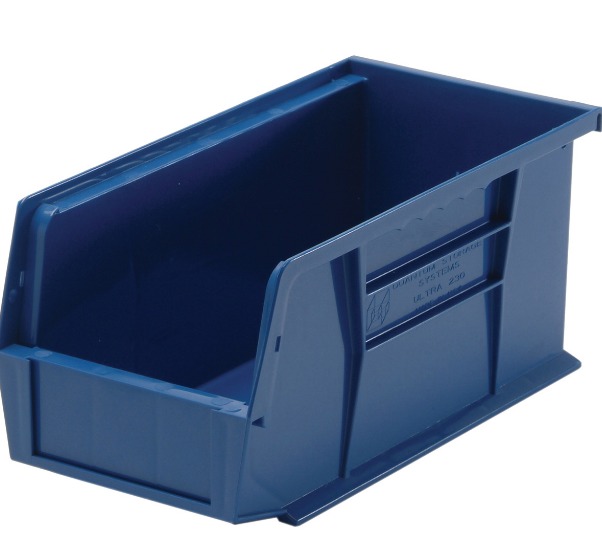
For example, consider a mould for a simple rectangular plastic box. The cavity has a relatively large and uniform cross - section, and the plastic can flow easily into it. The injection pressure needed for this mould might be relatively low, perhaps around 60 - 80 MPa.
Now, look at a mould for a small, detailed plastic figurine. The cavity has many small crevices, thin walls, and complex shapes. To fill all these details, the plastic needs to be forced into tight spaces, which requires a much higher injection pressure, potentially in the range of 150 - 200 MPa.
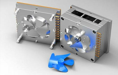
[Insert an image of a simple cavity and a complex cavity here for comparison]
In a case study of a company that produces small, high - precision plastic components for the electronics industry, they found that when they redesigned a mould to simplify the cavity geometry, the injection pressure could be reduced by 30%. This not only saved energy but also increased the lifespan of the injection moulding machine and the mould itself.
Gate Size and Type
The gate is the small opening through which the molten plastic enters the mould cavity from the runner. The size and type of the gate have a significant impact on the injection pressure.
A smaller gate size restricts the flow of plastic, increasing the resistance and thus requiring a higher injection pressure. For example, a pinpoint gate, which has a very small diameter (usually less than 1 mm), is often used for small, high - precision parts. Due to its small size, the plastic has to be forced through it with a relatively high pressure. In contrast, a larger gate, such as a side gate with a width of 3 - 5 mm, allows for a more unrestricted flow of plastic, reducing the injection pressure required.
The type of gate also matters. A direct gate, which connects the nozzle directly to the cavity, generally allows for a high - volume and high - speed flow of plastic, requiring less pressure compared to other gate types in some cases. A tunnel gate, on the other hand, is hidden within the mould and has a specific shape and orientation. It can be more difficult for the plastic to flow through a tunnel gate, increasing the pressure needed.
The following table compares the injection pressure requirements for different gate types and sizes for a standard plastic material:
| Gate Type | Gate Size | Injection Pressure (MPa) |
| Pinpoint Gate | 0.5 mm diameter | 120 - 150 |
| Side Gate | 3 mm width | 80 - 100 |
| Direct Gate | 5 mm diameter | 60 - 80 |
| Tunnel Gate | 1 mm diameter (tunnel) | 100 - 130 |
By carefully selecting the gate size and type based on the part design and material, manufacturers can optimize the injection pressure and the overall injection moulding process.
Machine Parameters
Screw Speed
The screw speed in an injection moulding machine affects the injection pressure in several ways. When the screw rotates faster, it pumps the molten plastic more quickly towards the nozzle. This increased flow rate can lead to an increase in the injection pressure if the resistance in the mould system (such as the narrow gates or long runners) remains the same.
In practical terms, if the screw speed is increased from 50 rpm to 100 rpm during the injection process for a given plastic material and mould setup, the injection pressure might increase by 20 - 30%. However, it's important to note that increasing the screw speed too much can also cause problems such as over - shearing of the plastic, which can degrade its properties.
In a production setting, it's recommended to start with a moderate screw speed and gradually adjust it based on the injection pressure readings and the quality of the molded parts. If the injection pressure is too low and the part is not filling properly, a slight increase in the screw speed can be tried. But if the pressure is too high and causing issues like flash (excess plastic seeping out of the mould), the screw speed should be decreased.
Injection Speed
The injection speed and injection pressure are closely related and have a significant impact on the quality of the molded parts. A higher injection speed means that the molten plastic is pushed into the mould cavity more rapidly. This can increase the injection pressure as the plastic has to overcome the resistance in the mould's channels and fill the cavity quickly.
However, an overly high injection speed can also lead to problems such as air entrapment (trapping air bubbles inside the part), jetting (where the plastic shoots into the cavity in a non - uniform stream), and excessive shear stress on the plastic. On the other hand, a too - low injection speed can result in incomplete filling of the mould cavity or poor surface finish due to the plastic cooling and solidifying before it fully fills the mould.
To optimize the injection speed to control the pressure, manufacturers can use a trial - and - error approach. Start with a medium injection speed and monitor the injection pressure and the quality of the parts. If the pressure is too high, reduce the injection speed. If the part is not filling properly, increase the injection speed slightly while also keeping an eye on the pressure. In some advanced injection moulding machines, there are sensors and control systems that can automatically adjust the injection speed based on the detected injection pressure to ensure a more consistent and high - quality injection process.
Measuring and Controlling Injection Pressure
Pressure Sensors
Pressure sensors are crucial components in injection moulding machines as they play a fundamental role in measuring injection pressure accurately. These sensors are typically installed at key points in the injection system, such as near the nozzle, in the runners, or within the mould cavity itself.
There are different types of pressure sensors used in injection moulding, with strain - gauge and piezoelectric sensors being two common ones. Strain - gauge sensors work on the principle of the piezoresistive effect. When pressure is applied to a strain - gauge element, usually made of a metal alloy, its electrical resistance changes proportionally to the applied pressure. This change in resistance is then measured and converted into an electrical signal, which can be easily processed by the machine's control system.
Piezoelectric sensors, on the other hand, operate based on the piezoelectric effect. Certain materials, like quartz or some ceramics, generate an electric charge when mechanical stress (pressure) is applied to them. The magnitude of this charge is directly related to the applied pressure.
The accuracy of pressure sensors is of utmost importance for precise pressure control. High - accuracy sensors, with an accuracy of ±0.5% or better, are preferred in many high - precision injection moulding applications. For example, in the production of medical devices or micro - electronic components, where even a slight deviation in pressure can lead to product defects, these accurate sensors ensure that the injection pressure is maintained within tight tolerances. A sensor with lower accuracy may introduce errors in the measured pressure, which could result in inconsistent part quality, such as variations in wall thickness or surface finish.
Closed - Loop Control Systems
Closed - loop control systems are essential for achieving precise control of injection pressure in modern injection moulding processes. These systems use feedback from pressure sensors to continuously adjust the injection process.
The basic principle of a closed - loop control system for injection pressure is as follows:
- Set - point determination: The operator first sets the desired injection pressure (the set - point) based on the material, mould design, and part requirements.
- Initial injection: The injection process starts, and the pressure sensor begins to measure the actual injection pressure.
- Feedback and comparison: The measured pressure value from the sensor is sent back (feedback) to the control system. The control system then compares this actual pressure with the pre - set set - point.
- Adjustment: If there is a difference between the actual and set - point pressures, the control system sends signals to the relevant components of the injection moulding machine, such as the hydraulic system or the servo - motor controlling the screw movement. For example, if the actual pressure is lower than the set - point, the control system may increase the flow rate of the hydraulic fluid to the injection unit, thereby increasing the injection pressure. If the pressure is too high, it will reduce the flow rate to lower the pressure.
Yigu Technology's View
As a non - standard plastic metal products custom Supplier, Yigu Technology places great emphasis on injection pressure in the injection moulding process. With years of experience in custom - manufacturing various plastic and metal products, we understand that precise control of injection pressure is the key to ensuring product quality.
During production, our team of experts carefully analyzes the material properties, mould design, and the specific requirements of each product. We use advanced pressure - measuring and controlling equipment to monitor and adjust the injection pressure in real - time. By maintaining the optimal injection pressure, we can guarantee that our products have consistent quality, accurate dimensions, and excellent surface finishes. Our technical strength and rich experience enable us to handle complex mould designs and challenging material combinations, always delivering high - quality products that meet or exceed customer expectations.