Rapid prototyping and tooling is an integrated development strategy that uses additive manufacturing and advanced machining to quickly create both prototype parts and short-run production molds, dramatically compressing the timeline from concept to market-ready product.
For manufacturing engineers, the traditional sequence of prototype, tool, then produce creates long delays and costly handoffs. Rapid prototyping and tooling redefines this sequence by enabling concurrent, iterative development of the part and the means to produce it. This guide explores how modern additive and digital manufacturing technologies allow engineers to create functional prototypes in days and production-capable molds in weeks, not months. We'll provide a practical framework for selecting the right process for each stage, choosing appropriate materials, and balancing the critical trade-offs between speed, cost, and durability. By mastering this integrated approach, engineering teams can de-risk designs earlier, validate manufacturing processes before major capital investment, and respond to market opportunities with unprecedented agility.
Introduction
In today's competitive landscape, the speed of product development is a decisive advantage. Rapid prototyping and tooling represents a paradigm shift from linear, stage-gated development to a fluid, iterative process. It combines two powerful capabilities: Rapid Prototyping (creating physical models directly from 3D CAD data) and Rapid Tooling (quickly fabricating molds or dies for low-to-medium volume production). The synergy between them is transformative. A prototype can now be a functional part made from production-grade material, and the tool to make that part can be created in parallel. This article provides manufacturing engineers with a comprehensive technical playbook. We will dissect how additive technologies like DMLS and SLA accelerate tool creation, outline material selection strategies for both prototypes and tools, and present a decision matrix for process selection. Through detailed case studies, we'll demonstrate how this integrated strategy manages risk, optimizes resources, and delivers a faster, more reliable path from concept to customer.
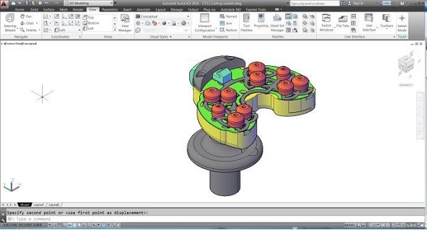
What Is Rapid Prototyping and Tooling?
Rapid prototyping and tooling is an interconnected product development methodology that leverages digital design data and agile manufacturing technologies to accelerate both the design validation and production readiness phases.
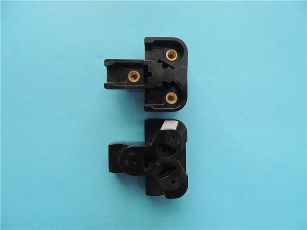
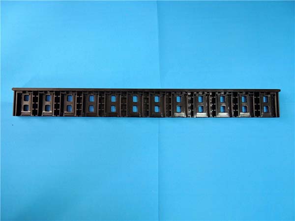
- Rapid Prototyping (RP): Focuses on creating physical representations of a design for fit, form, and functional testing. Technologies include 3D Printing (FDM, SLA, SLS), CNC machining, and vacuum casting.
- Rapid Tooling (RT): Focuses on creating the means of production—molds, dies, or fixtures—in a significantly reduced timeframe. Technologies include direct CNC machining of soft metals, additive manufacturing of metal tool inserts, and indirect methods like silicone molding.
The core value lies in their integration. Insights gained from functional rapid prototypes directly inform the design of the rapid tool, which can then be adjusted quickly and cost-effectively before any commitment to high-volume, hard tooling is made.
How Do Additive Technologies Accelerate Tool Creation?
Additive Manufacturing (AM), or 3D printing, has revolutionized rapid tooling by enabling geometries and efficiencies impossible with subtractive methods.
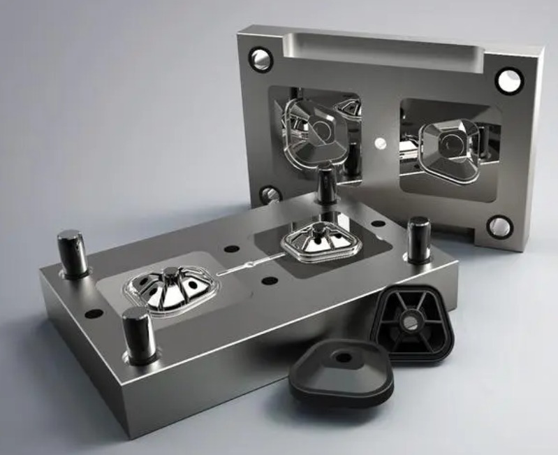
- Conformal Cooling Channels: This is the flagship application. In a traditionally machined mold, cooling channels are straight drilled lines, leading to uneven cooling, part warpage, and long cycle times. Metal 3D printing (DMLS) allows for the creation of conformal cooling channels that snake perfectly along the contour of the part cavity. This can improve cooling efficiency by up to 70%, reduce cycle times by 30-50%, and minimize part distortion.
- Consolidated Assemblies: Complex mold inserts with multiple parts, slides, and lifters can be 3D printed as a single, integrated component. This eliminates assembly errors, reduces part count, and can improve coolant flow and structural integrity.
- Rapid Iteration of Tool Geometry: If a design change is required after initial tooling trials, a new core or cavity insert can be 3D printed in days, whereas machining a new steel insert could take weeks.
Which Materials Best Serve Prototype vs. Tool Roles?
Material selection is driven by the purpose of the output—whether it's a prototype for testing or a tool for production.
Materials for Rapid Prototypes:
| Material (Process) | Key Properties | Best Prototype Role |
|---|---|---|
| ABS-like Resin (SLA/DLP) | Smooth finish, good detail, moderately strong. | Form & Fit models, visual prototypes, snap-fit testing. |
| Nylon (SLS/MJF) | Good strength, flexibility, and thermal resistance. No support structures needed. | Functional prototypes, housings, ductwork, living hinges. |
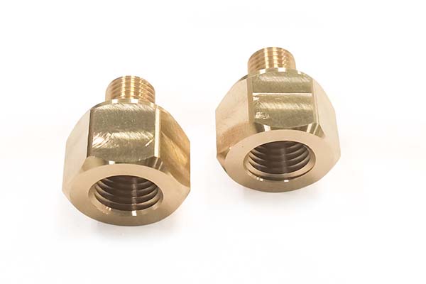
| Stainless Steel (DMLS) | Full metal strength and properties. | High-stress functional prototypes, engine components, end-use parts in aerospace/medical. |
| Urethane Casting Resin | Wide range of durometers (soft to rigid), can mimic production plastics. | Small batches of prototypes that need specific material properties when injection molding is not yet viable. |
Materials for Rapid Tools:
| Material (Process) | Key Tool Properties | Best Tooling Role & Life |
|---|---|---|
| Aluminum 7075-T6 (CNC) | Excellent thermal conductivity, easily machined. | Low-volume injection molds, pressure die-cast dies. Life: 1,000 - 10,000 shots. |
| Maraging Steel (DMLS) | Can be aged to high hardness (HRC 50+), enables conformal cooling. | Bridge/production molds for abrasive materials. Life: 10,000 - 50,000+ shots. |
| High-Temp SLA Resins | Withstands ~200-250°C, low cost for very short runs. | "Prototype" tools for <100 shots of low-melt temp plastics. |
| Silicone Rubber | Flexible, captures fine detail. | Indirect tooling for urethane casting of 10-50 prototypes. |
How to Select the Right Process for Each Stage?
Choosing the optimal path requires mapping the project's stage to the required output and constraints. The following framework guides this decision:
Stage 1: Conceptual Design & Early Fit Checks
- Goal: Visualize and check basic assembly.
- Recommended Process: SLA/DLP 3D Printing.
- Why: Fastest and most cost-effective for high-detail, aesthetic models. Material properties are secondary.
Stage 2: Functional & "Beta" Testing
- Goal: Test part under real-world conditions (stress, heat, fluid flow).
- Recommended Process: CNC Machining or Direct Metal Laser Sintering (DMLS) for metals; SLS or MJF for engineering plastics.
- Why: Provides parts in true engineering materials (aluminum, stainless, nylon) with accurate mechanical properties.
Stage 3: Pre-Production & Market Pilot
- Goal: Produce 50-5,000 units for market launch, clinical trial, or field testing.
- Recommended Process: Rapid Tooling for Injection Molding.
- Decision Point:
- For 50-500 simple parts: CNC-machined Aluminum Mold.
- For 500-5,000 complex parts needing fast cycles: DMLS Maraging Steel Mold with Conformal Cooling.
What Tolerances Can Be Held in Rapid Tools?
Managing expectations for accuracy is crucial, as rapid tools have different capabilities than seasoned production tools.
- CNC-Machined Aluminum Molds: Can consistently produce plastic parts with tolerances of ±0.001 to ±0.002 inches per inch (±0.1 to 0.2 mm per 100mm). This is suitable for the vast majority of functional and pre-production applications.
- 3D-Printed Metal (DMLS) Molds: Due to layer-by-layer construction and post-processing thermal effects, tolerances are generally wider: ±0.002 to ±0.005 inches per inch (±0.2 to 0.5 mm per 100mm). Critical mold surfaces are often finish-machined after printing to improve accuracy and surface finish.
- Key Consideration: The shrinkage of the final production plastic must be accurately calculated and designed into the rapid tool, just as with a production tool. This requires close collaboration between the design and tooling engineers.
How to Balance Speed, Cost, and Durability?
The central challenge of rapid tooling is navigating this triple constraint.
- The "Pick Two" Rule: In many cases, you can optimize for two of the three factors, but not all three simultaneously.
- Speed + Low Cost: A 3D-printed plastic or composite tool. Very fast and cheap, but durability is extremely low (<100 shots).
- Speed + Durability: A DMLS metal tool with conformal cooling. Can be produced in weeks and lasts for thousands of shots, but carries a high upfront cost.
- Low Cost + Durability: A CNC-machined aluminum tool. More durable than printed plastic and cheaper than DMLS steel, but machining takes longer than printing a plastic tool.
- Strategic Balancing: The key is to align the choice with the project's phase and business risk.
- Use low-cost, low-durability options for final design validation.
- Invest in durable rapid tools (aluminum/DMLS) for pilot runs that will generate revenue or critical test data.
- The cost of a rapid tool is often justified by the value of accelerated time-to-market and the risk mitigation it provides before committing to six-figure production tooling.
Case Studies: From Concept to Low-Volume Production
Case Study 1: Medical Device Startup – Surgical Tool
- Challenge: A startup needed to conduct cadaver labs and obtain regulatory feedback on a new stainless steel surgical instrument.
- Rapid Prototyping Path: Initial concept models were SLA printed. For functional testing, the parts were CNC machined from 17-4PH stainless steel to meet strength and sterilization requirements.
- Rapid Tooling Path: To produce 300 units for clinical trials, they used a CNC-machined aluminum injection mold for the plastic handle components.
- Outcome: The integrated approach allowed them to move from CAD to regulatory submission with functional parts in 12 weeks, a fraction of the traditional timeline.
Case Study 2: Automotive Supplier – Under-Hood Component
- Challenge: An automotive tier supplier needed to road-test a new engine manifold and supply 2,000 units for a limited vehicle run.
- Rapid Prototyping Path: Initial airflow prototypes were SLS printed in nylon for form and basic function.
- Rapid Tooling Path: For the final manifold in glass-filled nylon, they invested in a DMLS maraging steel mold with conformal cooling. The conformal channels managed the high heat of the material, preventing warpage and achieving a cycle time fast enough to meet the delivery schedule.
- Outcome: The rapid steel tool delivered production-quality parts for testing and the limited run, validating the design and manufacturing process before the program was approved for full-scale production tooling.
Conclusion
For the modern manufacturing engineer, rapid prototyping and tooling is no longer a series of disconnected services but a cohesive, strategic competency. By understanding how to leverage additive technologies for both part and tool fabrication, engineers can create a virtuous cycle of iteration and validation. The ability to produce functional prototypes in true materials and durable tools in weeks fundamentally changes the economics of product development, allowing for more innovative designs, lower-risk scaling, and decisive market speed. Mastering the selection of processes and materials at each stage—and intelligently balancing the trade-offs between speed, cost, and durability—empowers engineering teams to not just design products, but to reliably and efficiently orchestrate their journey to market.
Frequently Asked Questions (FAQ)
Can a rapid tool be upgraded into a production tool?
Generally, no. The materials and construction methods for rapid tools (aluminum, 3D-printed steel) are not designed for the millions of cycles required for high-volume production. However, a rapid tool is the perfect proving ground. The design, gate location, cooling layout, and process parameters validated with the rapid tool are directly transferred to the design of the hardened steel production tool, virtually eliminating costly rework.
What is the main difference between "direct" and "indirect" rapid tooling?
Direct Rapid Tooling creates the actual mold inserts (e.g., the core and cavity) directly via machining or 3D printing. Indirect Rapid Tooling first creates a master pattern (often 3D printed), which is then used to cast a mold from another material like silicone or soft metal. Indirect methods are typically faster and cheaper for very low quantities but offer poorer accuracy, surface finish, and tool life.
How does digital simulation (CAE) integrate with rapid prototyping and tooling?
Computer-Aided Engineering (CAE) is a critical enabler. Mold Flow Analysis simulates how plastic will fill and cool in a proposed mold design, identifying potential defects before any metal is cut or printed. This allows engineers to optimize the design of both the part and the rapid tool digitally, saving multiple physical iteration cycles. It is a cornerstone of the "first-time-right" aspiration in rapid tooling.
Is rapid tooling suitable for parts with undercuts or complex geometries?
Yes, but with planning. Undercuts require side-actions, sliders, or lifters in the mold. In rapid tooling, these mechanisms can be:
- Machined as separate components and assembled into an aluminum mold base.
- 3D printed as part of the monolithic insert in a DMLS tool, though this adds complexity.
While possible, adding actions increases the cost and lead time of the rapid tool. Good Design for Manufacturability (DFM) practice is to minimize undercuts if the sole purpose is a short pilot run.
Contact Yigu Technology for Custom Manufacturing.
At Yigu Technology, we provide integrated rapid prototyping and tooling solutions that streamline your entire product development cycle. Our expertise spans from creating high-fidelity functional prototypes to engineering and fabricating rapid injection molds for low-volume production.
We leverage a full spectrum of technologies—advanced 3D printing, precision CNC machining, and metal additive manufacturing—to deliver the right solution for each stage of your project. Our engineering team partners with you to develop a strategic roadmap, balancing speed, cost, and quality to meet your specific goals.
Ready to accelerate your product development with a unified rapid prototyping and tooling strategy? Contact Yigu Technology today to discuss your project and develop a customized plan.