Introduction
Definition and Importance of Injection Molded Components
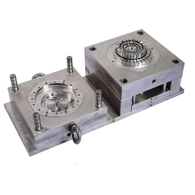
Injection molded components are parts produced through the injection molding process. This process involves injecting molten material, typically plastic, into a mold cavity. Once the material cools and solidifies, it takes on the shape of the cavity, resulting in a finished component. This manufacturing method is highly versatile and is used across a wide range of industries.
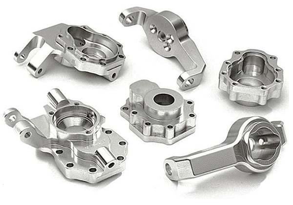
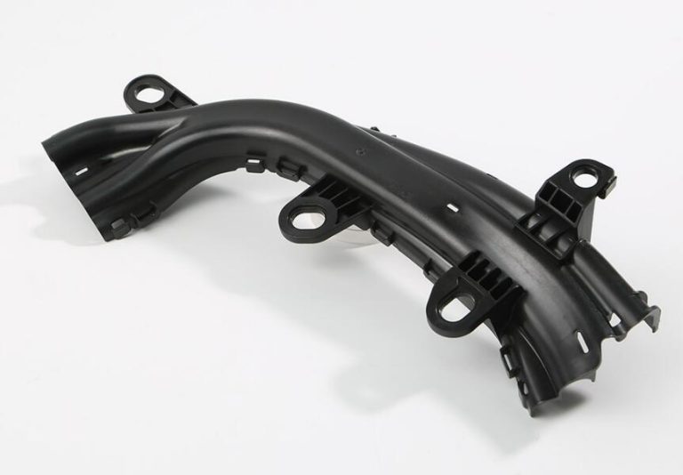
In the automotive industry, injection molded components are everywhere. From interior parts like dashboards, door panels, and seat covers to exterior components such as bumpers and body panels, injection molding provides the high - volume production capabilities needed to meet the demands of the automotive market. For example, a single car model may require thousands of identical plastic components, and injection molding can produce these parts efficiently and cost - effectively.
The electronics industry also heavily relies on injection molded components. Cases for smartphones, tablets, laptops, and other electronic devices are often made through injection molding. These components need to be precisely designed to house delicate electronic components while also providing protection from impacts and environmental factors. The ability to create complex shapes with tight tolerances makes injection molding an ideal choice for electronics manufacturers.
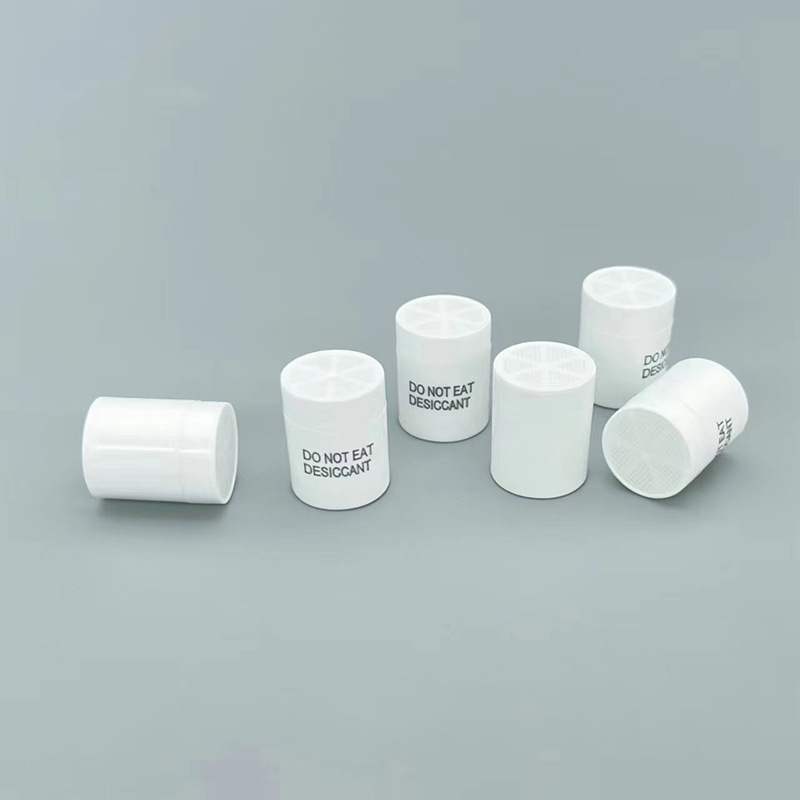
In the medical field, injection molded components are used in a variety of applications, including disposable syringes, medical device housings, and prosthetics. The high - precision nature of injection molding ensures that these components meet strict medical standards and regulations, guaranteeing patient safety.
Given the wide - spread use of injection molded components in these and other industries, the design of intricate injection molded components becomes crucial. To achieve high - quality, functional, and cost - effective components, there are 10 important rules that designers and engineers should follow.
Rule 1: Material Selection
Consider Material Properties
The choice of material for injection - molded components is fundamental as it directly impacts the component's performance, functionality, and cost - effectiveness. There are several common materials used in injection molding, each with its own set of properties.
ABS (Acrylonitrile Butadiene Styrene)
- Mechanical Properties: ABS offers a good balance of mechanical properties. It has high impact strength, which means it can withstand sudden forces without cracking or breaking easily. For example, in the production of automotive interior components like dashboards, ABS can endure the impact from passengers during sudden stops or collisions. Its tensile strength allows it to maintain its shape under tension, and it has a relatively high modulus, providing stiffness to the component.
- Chemical Stability: It is resistant to many chemicals, including oils, greases, and some solvents. This makes it suitable for applications where the component may come into contact with various substances, such as in industrial equipment housings.
- Liquidity: ABS has a moderate flowability during the injection molding process. This allows it to fill the mold cavities relatively easily, but it may require higher injection pressures compared to some more flow - friendly materials. It can be used to create complex - shaped components with moderate detail.
PP (Polypropylene)
- Mechanical Properties: PP is a lightweight material with good strength - to - weight ratio. It has excellent flexural strength, which makes it ideal for applications like plastic hinges. For instance, the lids of many food containers are made of PP because they can be repeatedly opened and closed without breaking. However, its impact strength at low temperatures is relatively poor.
- Chemical Stability: It has high chemical resistance, especially to organic solvents and acids. This property makes it suitable for use in chemical storage containers and components in chemical processing equipment.
- Liquidity: PP has good flowability, which enables it to be used in high - volume production of thin - walled components. It can be processed at relatively low temperatures, reducing energy consumption during the injection molding process.
PC (Polycarbonate)
- Mechanical Properties: PC is known for its outstanding impact resistance, often used in applications where high - impact protection is required, such as in safety helmets and automotive headlamp lenses. It also has high tensile strength and dimensional stability, maintaining its shape accurately over a wide range of temperatures.
- Chemical Stability: PC is resistant to many chemicals, but it is sensitive to some strong alkalis and solvents. It has good weather resistance, making it suitable for outdoor applications.
- Liquidity: PC has a relatively low flowability compared to ABS and PP. It requires higher processing temperatures and injection pressures to fill the mold cavities. However, its ability to form complex shapes with high precision compensates for this drawback in applications where intricate designs are crucial, like in optical components.
In summary, when designing intricate injection - molded components, it is crucial to match the material properties with the product requirements. If a component needs to be lightweight, have good chemical resistance, and be cost - effective for high - volume production, PP might be a suitable choice. For components that require high - impact resistance and dimensional stability, PC could be the better option. And if a balance of mechanical properties, chemical stability, and moderate complexity in shape is needed, ABS might be the ideal material.
Rule 2: Wall Thickness Design
Uniform Wall Thickness Principle
Maintaining a uniform wall thickness is of utmost importance in the design of intricate injection - molded components. When the wall thickness is uneven, it can lead to a variety of issues during the injection molding process.
One of the most common problems caused by uneven wall thickness is shrinkage. During the cooling phase of injection molding, the material in thicker sections cools more slowly than that in thinner sections. As a result, the thicker areas shrink more, creating internal stresses within the component. These internal stresses can cause the surface of the component to develop sink marks, which are depressions on the surface that are aesthetically unappealing and can also indicate potential structural weaknesses. For example, in the production of a plastic toy with an uneven - wall - thickness body, sink marks may appear on the thicker parts of the toy, reducing its marketability.
Warpage is another significant issue associated with non - uniform wall thickness. The differential cooling rates between thick and thin sections cause the component to distort as it cools. This distortion can lead to problems in assembly, as the warped component may not fit properly with other parts. In the automotive industry, if a plastic interior component such as a dashboard panel has an uneven wall thickness, it may warp during molding, making it difficult to install in the vehicle and potentially affecting the overall quality of the interior.
The appropriate wall thickness for injection - molded components varies depending on the product type. For small, delicate components like electronic device buttons, a relatively thin wall thickness in the range of 0.5 - 1.5 mm can be sufficient. These components do not need to withstand significant mechanical stress and can be made thin to reduce material usage and production costs.
For medium - sized components such as household appliance housings, a wall thickness between 1.5 - 3 mm is commonly used. These components need to have enough strength to protect the internal components and withstand normal handling and use. For example, the housing of a blender or a toaster typically has a wall thickness in this range to ensure durability while maintaining an acceptable weight and cost.
Large - scale components, like automotive bumpers, usually require a thicker wall thickness, often in the range of 3 - 5 mm. These components must be able to absorb impacts and provide protection to the vehicle and its occupants. The increased wall thickness helps to enhance the mechanical properties of the bumper, making it more resistant to deformation during collisions.
Rule 3: Draft Angle Determination
Function of Draft Angle
The draft angle, also known as the 脱模斜度 in Chinese, is an essential factor in the design of intricate injection - molded components. Its primary function is to facilitate the smooth removal of the molded part from the mold cavity. During the injection molding process, after the molten material cools and solidifies, it adheres to the mold surfaces due to shrinkage. Without an adequate draft angle, the component can become stuck in the mold, leading to difficulties in the 脱模 process.
For example, in the production of small plastic figurines, if the draft angle is insufficient, the figurines may break during 脱模 as the force required to separate them from the mold exceeds their structural strength. Even if the component does not break, surface damage such as scratches or scuff marks can occur, which is unacceptable for products with high - quality surface requirements, like consumer electronics housings.
The lack or inadequacy of the draft angle can also lead to increased production time. Workers may need to spend extra time and effort to remove the stuck components from the mold, and in some cases, the mold may need to be disassembled to free the part. This not only reduces production efficiency but also increases the risk of mold damage.
Recommended Draft Angle Values
The appropriate draft angle varies depending on several factors, including the material used and the surface roughness of the component. For materials with low friction coefficients, such as polyethylene (PE) and polypropylene (PP), a relatively small draft angle of 0.5 - 1 degree may be sufficient. These materials have good self - lubricating properties, which makes it easier for the molded parts to slide out of the mold.
On the other hand, materials with higher friction coefficients, like polycarbonate (PC) and acrylonitrile - butadiene - styrene (ABS), generally require a larger draft angle, typically in the range of 1 - 1.5 degrees. PC, for instance, has a relatively high modulus and can adhere strongly to the mold surface during cooling. A larger draft angle helps to overcome this adhesion and ensure smooth 脱模.
When it comes to surface roughness, components with smooth surfaces can get away with smaller draft angles. For example, if a component has a mirror - like finish, a draft angle of 0.5 - 1 degree may be adequate. However, for components with textured or rough surfaces, a larger draft angle is necessary. If a plastic component has a leather - like texture on its surface, a draft angle of 1.5 - 3 degrees may be required to ensure that the part can be removed from the mold without damage.
Rule 4: Radius Design
The Significance of Rounding Corners
Rounding the corners of injection - molded components, or adding radii, is a crucial design aspect that significantly impacts the component's structural integrity. Sharp corners in injection - molded components create stress concentration points. When the component is subjected to mechanical stress, such as during assembly, normal use, or in - service loading, these sharp corners act as weak points where the stress accumulates.
To better illustrate this, let's consider a simple example of a rectangular - shaped injection - molded plastic bracket. If the bracket has sharp corners, as shown in Figure 1 (left), when a force is applied, the stress distribution is highly non - uniform. The stress levels are much higher at the sharp corners compared to the rest of the component. This can lead to premature cracking or failure of the component, especially if it is made of a brittle material or is repeatedly loaded.
In contrast, when the same bracket has rounded corners, as shown in Figure 1 (right), the stress is more evenly distributed across the component. The radius at the corners allows the stress to spread out, reducing the likelihood of stress - induced failures. This is because the rounded shape provides a smoother transition for the stress lines, rather than having them concentrated at a single point as in the case of sharp corners.
In addition to improving the structural integrity, radius design also has positive effects on the injection molding process itself. During the injection of the molten material into the mold cavity, the flow of the material is smoother around rounded corners. Sharp corners can cause the molten plastic to flow erratically, leading to issues such as flow marks, weld lines, and incomplete filling of the mold cavity. Rounded corners, on the other hand, promote a more laminar flow of the molten plastic, resulting in a more uniform and defect - free component.
For example, in the production of a complex - shaped plastic housing for an electronic device, if the internal corners of the housing are sharp, the molten plastic may have difficulty filling those areas completely, leading to voids or thin - walled sections. By adding radii to these corners, the plastic can flow more easily, ensuring that the entire mold cavity is filled properly and that the final component has consistent wall thickness and quality.
Rule 5: Gate Design
Types and Selection of Gates
Gate design is a critical aspect of injection - molded component design as it directly affects the filling of the mold cavity, the quality of the final product, and the post - processing requirements. There are several common types of gates, each with its own characteristics in terms of filling effect, product appearance, and gate removal difficulty.
Side Gates
- Filling effect: Side gates are relatively versatile in terms of filling. They can be used for a wide range of part sizes and shapes. For medium - sized components, a side gate can provide a balanced flow of molten plastic into the mold cavity. For example, in the production of a plastic storage box, a side gate can ensure that the plastic evenly fills the rectangular - shaped cavity. However, compared to some other gate types, side gates may sometimes cause uneven flow patterns, especially for complex - shaped parts. This can lead to issues like weld lines, which occur when two streams of molten plastic meet during filling.
- Product appearance: One of the main drawbacks of side gates is their impact on product appearance. After the injection molding process, the side gate remains attached to the product, and it needs to be manually trimmed off. This often leaves a visible scar or mark on the surface of the product. For products with high - end aesthetic requirements, such as consumer electronics housings or high - end packaging, this can be a significant disadvantage.
- The difficulty of gate removal: Removing a side gate can be relatively straightforward in some cases but can also be time - consuming and require careful handling. If the gate is thick or the material is tough, trimming it without damaging the product can be a challenge. Special tools like sharp knives or trimming machines are usually used, and there is a risk of leaving behind burrs or uneven surfaces if the operation is not performed correctly.
Pin Gates
- Filling effect Pin gates are known for their ability to provide a high - pressure, focused flow of molten plastic into the mold cavity. This makes them suitable for small, intricate components where precise filling is crucial. For example, in the production of small plastic gears or electronic connectors, the small diameter of the pin gate allows for accurate control of the plastic flow, ensuring that all the fine details of the component are filled properly. The high - pressure injection through the pin gate also helps to achieve good dimensional accuracy in the final product.
- Product appearance: Pin gates are highly favored when it comes to product appearance. Since the gate is small in diameter (usually in the range of 0.5 - 2 mm), the mark left after gate removal is minimal. This makes pin gates ideal for products where a smooth, blemish - free surface is required, such as optical components or high - end consumer goods.
- The difficulty of gate removal: While the small size of the pin gate is an advantage for product appearance, it can pose challenges in gate removal. Due to its small diameter, the gate can be fragile, and there is a risk of it breaking off during removal. Specialized tools like fine - tipped cutters or laser - based removal systems may be required to ensure clean and precise removal without damaging the surrounding area of the product.
Submarine Gates (also known as Tunnel Gates)
- Filling effect: Submarine gates offer a unique filling advantage as they are hidden within the mold. This allows for a more uniform flow of molten plastic into the cavity, reducing the likelihood of flow - related defects. The gate is typically angled, which helps to guide the plastic smoothly into the mold. For products with complex internal geometries or for parts where a straight - through flow from a traditional gate would be problematic, submarine gates can provide a better solution. For instance, in the production of a plastic bottle cap with internal threads, a submarine gate can ensure that the plastic fills the threaded area evenly without causing any disruptions to the thread formation.
- Product appearance: These gates are highly desirable for products with strict aesthetic requirements because they do not leave any visible marks on the product surface. Since the gate is located inside the mold and is removed during the ejection process, there is no need for post - processing to remove a visible gate mark. This makes them popular in industries such as automotive interior component manufacturing, where the appearance of the final product is of utmost importance.
- The difficulty of gate removal: The removal of submarine gates is integrated into the ejection process of the mold. As the product is ejected from the mold, the gate is sheared off. This generally requires careful design of the gate and ejection system to ensure that the gate is cleanly removed without leaving any residue or causing damage to the product. However, compared to side gates that require manual trimming, the automated removal process of submarine gates can be more efficient in high - volume production scenarios.
The following table summarizes the key differences between these gate types:
| Gate Type | Filling Effect | Product Appearance | Gate Removal Difficulty |
| Side Gate | Versatile, but may cause uneven flow and weld lines | Leaves visible marks after removal | Manual trimming, can be challenging for thick gates |
| Pin Gate | High - pressure, precise filling for small components | Minimal mark after removal | Requires specialized tools due to small size |
| Submarine Gate | Uniform flow, suitable for complex geometries | No visible marks on surface | Integrated with ejection process, requires careful design |
In conclusion, the selection of the gate type for an injection - molded component depends on a variety of factors, including the product's size, shape, complexity, aesthetic requirements, and the production volume. Designers and engineers must carefully evaluate these factors to choose the most appropriate gate type for optimal component quality and production efficiency.
Yigu Technology's View
As a non - standard plastic metal products custom Supplier, Yigu Technology deeply understands the significance of these 10 rules in the design of injection - molded components. In our practical experience, strict compliance with these rules is the key to producing high - quality products.
For material selection, we have an in - depth understanding of various materials. We know that different materials have different properties, and we can accurately match materials with product requirements according to the actual situation of the project. For example, in a project that requires high - temperature resistance and excellent mechanical properties, we chose a special engineering plastic, which successfully met the customer's needs.
In terms of wall thickness design, we use advanced simulation software to analyze and optimize the wall thickness of components to ensure uniform wall thickness as much as possible. This not only improves the quality of products but also reduces production costs.
Regarding the draft angle, we have a set of mature design standards. Based on the material characteristics and surface requirements of the component, we can accurately determine the appropriate draft angle to ensure smooth demolding and high - quality product surfaces.
In general, by strictly following these 10 rules, Yigu Technology can continuously improve the quality of injection - molded components and provide customers with more satisfactory products and services.
Conclusion
In conclusion, the design of intricate injection - molded components is a complex and multi - faceted process. The 10 rules we've discussed - material selection, wall thickness design, draft angle determination, radius design, gate design, runner system design, ventilation design, cooling system design, tolerance design, and design for assembly - are not just guidelines but essential principles that can make or break the quality, functionality, and cost - effectiveness of the final components.
By carefully selecting the right material, maintaining uniform wall thickness, determining appropriate draft angles and radii, designing optimal gate and runner systems, ensuring proper ventilation and cooling, setting accurate tolerances, and considering assembly - friendly features, engineers and designers can create injection - molded components that meet the highest standards.
These rules are applicable across a wide range of industries, from automotive and electronics to medical and consumer goods. Whether you are a seasoned professional or just starting in the field of injection - molded component design, I encourage you to apply these rules in your projects. Each rule plays a crucial role in the overall design process, and by adhering to them, you can reduce production costs, minimize defects, and improve the performance and reliability of your injection - molded components.
FAQ
1. How do I choose the right material for my injection - molded component?
Consider the component's requirements in terms of mechanical properties (such as impact strength, tensile strength), chemical stability, and flowability during injection molding. For example, if high - impact resistance is needed, materials like PC or ABS might be suitable. Also, think about cost - effectiveness and production volume.
2. Why is a uniform wall thickness important in injection - molded components?
A uniform wall thickness prevents issues like shrinkage, warpage, and sink marks. Thicker sections cool more slowly than thinner ones, causing internal stresses. These stresses can lead to cosmetic defects and structural weaknesses, so maintaining a consistent wall thickness helps ensure a high - quality, functional component.
3. What are the common methods for ventilation in injection - molded component design?
Common methods include parting surface ventilation, where a small gap at the parting surface allows gases to escape. Ventilation grooves, typically machined on the parting surface, are also widely used. For complex - shaped molds or high - precision components, permeable steel can be used to allow gases to pass through while maintaining the mold's structural integrity.