Introduction
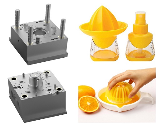
Molds are the bridge between digital designs and physical products. In industries where mistakes are costly—automotive, medical, electronics—mold quality is paramount. The technology that makes this quality possible is CNC machining. It transforms raw steel into the detailed, durable tools needed for mass production.
This guide explores advanced strategies and complete workflows that define high-quality CNC mold making. You will learn about CAD/CAM optimization, multi-axis machining strategies, high-speed machining techniques, tool monitoring, and finishing processes. Our goal is to provide useful knowledge that improves precision, efficiency, and quality in your mold-making operations.
How Do You Optimize CAD/CAM Workflows?
A successful mold starts long before any cutting begins. The foundation lies in a well-planned CAD/CAM workflow. This digital phase is where manufacturability is decided, errors are prevented, and the plan for physical creation is perfected.
From Concept to Code
The journey from a 3D model to a finished mold cavity follows a careful path.
1. Mold Design in CAD: This is the planning stage. For mold making, we build critical features directly into the design. This includes defining the parting line, applying precise draft angles, separating the model into core and cavity halves, and designing complex cooling channels. Material-specific shrinkage compensation is added to ensure final parts meet size specifications. Design for Manufacturability (DFM) analysis identifies features that would be difficult or impossible to machine before moving to CAM.
2. Toolpath Generation in CAM: The validated CAD model is imported into CAM to be translated into machine instructions. This is a strategic process. We select cutting strategies based on mold shape and material. Operations typically include:
- High-efficiency roughing to remove bulk material
- Semi-finishing to refine the shape
- High-precision finishing to achieve final surface quality
Advanced CAM software provides simulation features to visualize machining, detect potential collisions, and estimate machining time.
3. Post-Processing and Verification: The final digital step converts generic toolpath data into machine-specific G-code. Each machine brand (Haas, Fanuc, Siemens) has its own language, making a properly configured post-processor essential. Advanced verification software uses a "digital twin" of the physical machine to run a final simulation, protecting against costly crashes.
What Multi-Axis CNC Strategies Should You Use?
Modern products demand molds with complex shapes. Deep ribs, curved surfaces, and undercuts are often impossible with traditional 3-axis machining. Understanding when to use 3-axis, 3+2, and continuous 5-axis machining is fundamental to balancing cost, time, and quality.
3-Axis Machining
3-axis machining—where the cutting tool moves in X, Y, and Z axes simultaneously—is the workhorse for many mold-making operations. It is highly effective and cost-efficient for molds with relatively simple shapes: open cavities, straight walls, and no undercuts.
Limitation: To machine features on different faces, the part must be manually rotated and re-positioned. This is time-consuming and introduces potential for cumulative location errors.
3+2 Axis Machining
Often called positional 5-axis machining, this approach uses two rotational axes (A and B) to lock the workpiece at a compound angle. The machine then executes a standard 3-axis cutting program.
Primary benefit: Machining five sides of a mold block in a single setup. This is perfect for drilling angled cooling channels, milling deep pockets without excessively long tools, and creating minor undercuts. It significantly improves accuracy and cuts production time.
Continuous 5-Axis Machining
Continuous 5-axis machining represents the peak of CNC capability. All five axes (X, Y, Z, A, B) move simultaneously, allowing the tool to follow intricate, continuously changing surface contours. This is essential for molds with organic shapes—medical implants, aerospace turbine blades.
Key advantage: Maintaining an optimal cutting position, keeping the tool tangent to the workpiece surface. This allows shorter, more rigid tools, minimizing deflection and vibration. The result is superior surface finish requiring less manual polishing.
| Machining Type | Axis Movement | Best For | Pros | Cons |
|---|---|---|---|---|
| 3-Axis | Simultaneous X, Y, Z | Open cavities, simple cores, roughing | Simple to program, fast for basic shapes, cost-effective | Multiple setups, limited tool access |
| 3+2 Axis | 3-axis cutting on fixed angled workpiece | Angled holes, deep pockets, 5-sided features | Single-setup efficiency, improved accuracy | Cannot machine complex curved surfaces in one pass |
| Continuous 5-Axis | Simultaneous X, Y, Z, A, B | Complex curved surfaces, undercuts, conformal cooling | Superior surface finish, access to all features, shorter tools | High machine cost, complex programming |
What Is High-Speed Machining and Why Does It Matter?
High-Speed Machining (HSM) is a transformative strategy, particularly when working with hardened tool steels. HSM pairs high cutting speeds with high feed rates, using shallow axial depth of cut (ADOC) and small radial depth of cut (RDOC). This "light and fast" approach changes the physics of cutting. Heat is removed by forming small, hot chips that are thrown clear, leaving both tool and workpiece relatively cool.
Defining HSM
HSM uses specialized toolpaths that maintain constant tool engagement and avoid sharp corners that cause tool shock. CAM systems generate these paths using algorithms like:
- Trochoidal milling: Circular "looping" motion to clear channels wider than the tool diameter
- Peel milling: Progressive material removal
- High-speed contouring: Maintaining consistent tool engagement
This controlled engagement allows dramatically higher feed rates and deeper axial cuts than conventional methods.
Benefits in Mold Fabrication
Machining hardened materials: HSM efficiently machines tool steels like H13, P20, and S7 after heat treatment (45–65 HRC). This hard milling allows us to machine molds to final dimensions in their stable, hardened state, eliminating an entire stage of the process and associated inaccuracies.
Superior surface finish: Light radial engagement and high cutting speeds reduce cutting forces and tool deflection. The result is a much smoother surface directly off the machine, reducing manual polishing time by 50 to 80 percent.
Reduced lead times: While depth of cut is small, high feed rates mean overall material removal rate (MRR) for finishing operations is significantly higher than conventional methods.
| Material | Hardness (HRC) | Cutting Speed (Vc) | Feed per Tooth (fz) | Notes |
|---|---|---|---|---|
| P20 Tool Steel | ~32 HRC | 200–400 m/min | 0.1–0.3 mm | Pre-hardened; excellent for HSM roughing and finishing |
| Hardened H13 | ~52 HRC | 100–250 m/min | 0.05–0.15 mm | Requires rigid setup; heat managed in the chip |
| Hardened S7 | ~56 HRC | 80–200 m/min | 0.04–0.12 mm | Very tough; requires conservative parameters |
Machine and Tooling Needs
HSM requires:
- High-speed spindle (20,000 RPM or higher)
- Fast acceleration and deceleration
- Advanced control with "look-ahead" capabilities
- Precision-balanced tool holders (HSK or shrink-fit)
- Solid carbide end mills with advanced coatings (TiAlN, AlCrN)
How Do You Ensure Tool Longevity?
In high-value mold making, a broken tool can be catastrophic. During a final finishing pass, a snapped end mill can gouge the mold surface, scrapping a steel block with hundreds of hours of machining invested. Proactive tool wear monitoring is essential.
Why Proactive Monitoring Matters
A worn tool requires higher cutting forces, leading to deflection, dimensional inaccuracies, and poor surface finish requiring costly polishing. A proactive strategy tracks tool health and replaces it at the optimal moment—before performance degrades or failure occurs.
Monitoring Methodologies
Manual & Operator-Led Monitoring:
- Visual: Regular inspection reveals chipping, rounding of corners, or built-up edge (BUE)
- Auditory: A sharp tool produces a clean hissing sound; dull tools cause rumbling, screeching, or chattering
- Tactile: Experienced operators feel changes in vibration
- Part inspection: Degrading surface finish or burrs indicate tool wear
Machine-Based (Indirect) Monitoring:
- Spindle load monitoring: Tracking power consumption; gradual load increase indicates wear; sudden spikes signal imminent failure
- Acoustic emission (AE) sensors: Detect high-frequency stress waves from material deformation
- Vibration analysis: Monitors vibration signature; deviations from baseline indicate issues
Direct Monitoring Systems:
- In-machine probing/laser systems: Automatically measure tool length and diameter between operations; detect broken tools or wear; automatically switch tools when tolerances are exceeded
- Machine vision: High-resolution cameras capture images of cutting edges; software quantifies wear and defects
What Finishing Processes Complete the Mold?
After CNC machining, mold surfaces must be treated to achieve the required quality and texture. These post-CNC processes fall into two categories: polishing (smoothness and gloss) and texturing (functional or aesthetic patterns).
Achieving the Perfect Shine
Mold polishing removes microscopic machining marks. The goal is a specific level of smoothness that translates to gloss and clarity in the final plastic part. This is critical for optical components (lenses, light pipes) and consumer products demanding high-gloss "Class-A" appearance.
The industry standard is the SPI (Society of the Plastics Industry) finish specification.
| SPI Grade | Description | Typical Application |
|---|---|---|
| A-1 | Grade #3 Diamond Buff | Optical lenses, mirrors, high-polish visors |
| A-2 | Grade #6 Diamond Buff | High-gloss cosmetic parts, reflective surfaces |
| A-3 | Grade #15 Diamond Buff | High-quality gloss parts |
| B-1 | 600 Grit Paper | Medium-gloss parts |
| B-2 | 400 Grit Paper | Medium-low gloss parts |
| C-1 | 600 Grit Stone | Low-gloss, non-cosmetic surfaces |
| D-1 | Dry Blast #11 Glass Bead | Satin finish |
Manual polishing relies on skilled polishers using abrasive stones, emery papers, and diamond pastes. For simpler geometries, automated polishing cells offer consistency and speed.
Adding Function and Feel
Mold texturing creates patterns transferred to every molded part. Textures provide improved grip, reduced friction, or specific light diffusion properties.
Chemical photo-etching: Applies a photosensitive mask, exposes it to a pattern, and uses acid to etch unprotected areas. Capable of complex natural patterns like leather or woodgrain.
Laser texturing/ablation: A high-power laser is controlled by a 5-axis system to precisely ablate material. Creates patterns with perfect repeatability and sharp detail. Ideal for geometric patterns, micro-textures, and brand logos.
Abrasive blasting: Propels media (glass beads, aluminum oxide) against the mold surface. Creates uniform matte or satin finishes (SPI D-grade standards).
Yigu Technology’s Perspective
As a custom supplier of non-standard plastic and metal products, we view CNC precision tooling as the synthesis of digital precision and physical craft. Our approach integrates:
- Optimized CAD/CAM workflows that define manufacturability before cutting begins
- Strategic multi-axis machining that conquers complex geometries
- High-speed machining that efficiently processes hardened materials
- Proactive tool monitoring that guards quality and prevents catastrophic failures
- Skilled finishing that brings molds to required perfection
This integrated approach ensures digital intent is flawlessly translated into physical tools that perform with unwavering precision and durability.
Conclusion
CNC precision tooling is the foundation of high-quality mold fabrication. Optimized CAD/CAM workflows ensure manufacturability and error prevention. Multi-axis strategies—3-axis, 3+2, and continuous 5-axis—balance cost, time, and complexity. High-speed machining enables efficient processing of hardened materials with superior surface finishes. Proactive tool monitoring protects valuable workpieces and maintains quality. Finishing processes—polishing and texturing—bring molds to their final required state.
Mastery lies in the seamless integration of this entire process chain. When executed well, it transforms digital designs into physical tools that deliver precision, durability, and consistent quality.
FAQ
What is the difference between 3+2 and continuous 5-axis machining?
3+2 machining (positional 5-axis) locks the workpiece at an angle and performs standard 3-axis cutting. It is ideal for machining five sides in one setup and for angled features. Continuous 5-axis machining moves all axes simultaneously, allowing the tool to follow complex curved surfaces. It delivers superior surface finish and access to undercuts but requires more complex programming and higher machine costs.
How does high-speed machining benefit mold fabrication?
HSM enables efficient machining of hardened tool steels (45–65 HRC) through "hard milling," eliminating the need for slow grinding or EDM finishing. It produces superior surface finishes directly off the machine, reducing manual polishing by 50–80 percent. It also reduces lead times through higher material removal rates despite shallow depths of cut.
Why is tool wear monitoring important in mold making?
A broken tool during final finishing can scrap a mold block with hundreds of hours of machining invested. Gradual wear degrades dimensional accuracy and surface finish, leading to out-of-spec parts and costly rework. Proactive monitoring—using spindle load, acoustic emission, vibration analysis, or in-machine probing—enables predictive tool changes that maximize tool life while protecting the workpiece.
Contact Yigu Technology for Custom Manufacturing
Looking for precision tooling that delivers consistent quality? Yigu Technology specializes in custom non-standard plastic and metal products. Our team combines advanced CNC capabilities with skilled craftsmanship to produce molds that perform.
Reach out today to discuss your next project. Let us help you achieve precision at every stage.