Introduction
You have a great product idea. You’ve designed the part. Now comes the critical question: how do you create the tool that will make it?
Building an injection mold is a complex process that combines engineering precision, material science, and practical manufacturing experience. A well-designed mold produces consistent, high-quality parts for hundreds of thousands of cycles. A poorly designed mold leads to defects, delays, and costly rework.
This guide walks you through the seven essential steps of injection mold design and construction. Whether you’re new to molding or looking to refine your process, you’ll learn the fundamentals that turn a design into a production-ready tool.
Step 1: Product Design and Analysis
Design Considerations
Before you design the mold, you must thoroughly understand the product. Every feature of your part affects how the mold will be built.
| Design Factor | Impact on Mold |
|---|---|
| Product shape | Complex shapes may need slides or lifters for undercuts |
| Dimensions | Tight tolerances require precise machining and stable materials |
| Wall thickness | Uneven walls cause warpage and sink marks |
| Surface finish | High-gloss surfaces demand polished mold steel |
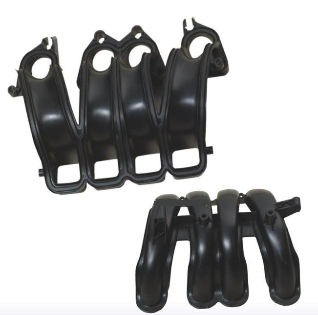
Real example: A toy figure with protruding arms and legs requires a mold with sliding components. Without slides, the part would be impossible to eject. Adding slides increases mold complexity and cost—but it’s the only way to produce the design.
Material Selection
The plastic you choose directly impacts mold design. Different materials have different shrinkage rates, flow characteristics, and cooling requirements.
| Material | Shrinkage Rate | Mold Design Impact |
|---|---|---|
| PP (Polypropylene) | 1.0–2.5% | Mold cavities must be oversized to compensate |
| ABS | 0.4–0.9% | Tighter tolerances achievable |
| PC (Polycarbonate) | 0.5–0.7% | High temperatures; requires hardened steel |
| PEEK | 0.1–0.5% | Extreme temperatures; specialized tooling |
Select material based on:
- End-use application (structural, cosmetic, medical)
- Cost targets
- Manufacturability
- Environmental requirements (sterilization, UV resistance)
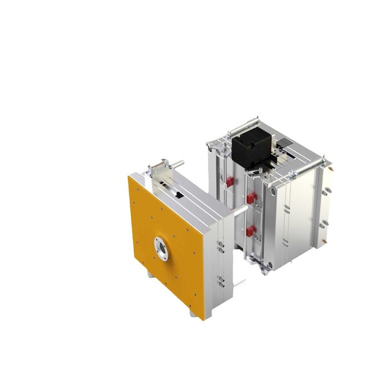
Step 2: Mold Concept Design
Sketching the Initial Idea
With product design finalized, you begin shaping the mold concept. Two critical decisions come first:
Parting line: Where the two mold halves meet. For a simple box, it’s a horizontal line. For complex shapes, the parting line must be carefully positioned to:
- Allow easy part ejection
- Minimize visible lines on finished product
- Simplify mold construction
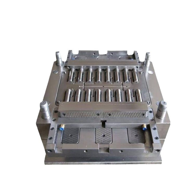
Number of cavities: More cavities increase productivity—but also complexity. A 32-cavity mold for small buttons produces 32 parts per cycle, but each cavity must receive plastic evenly, and cooling must be uniform across all.
| Cavity Count | Productivity | Complexity | Typical Use |
|---|---|---|---|
| 1 | Low | Simple | Prototypes, large parts |
| 2–4 | Medium | Moderate | Medium-volume production |
| 8–32+ | High | Complex | High-volume small parts |
Function and Structure Planning
Now plan the mold’s core systems:
Gating system: Guides molten material from injection unit to cavity.
- Direct gate (sprue): Simple, leaves large mark—good for large parts
- Pin-point gate: Small diameter, leaves tiny mark—ideal for precision parts
Runner system: Connects gate to cavities. Cross-sectional area affects flow rate and pressure drop. Larger runners reduce pressure but waste material.
Cooling system: Drilled channels circulate coolant to remove heat. For thick-walled parts, channels should be larger and closer to the cavity. Uneven cooling causes warpage.
Ejection system: Removes solidified parts. Ejector pins are placed strategically—often at the base or areas with strong mold adhesion. Thin-walled parts need more, smaller pins to distribute force evenly.
Step 3: CAD Modeling
The Role of CAD in Mold Design
Computer-Aided Design (CAD) has revolutionized mold making. It offers:
- Accuracy: Input precise dimensions—essential for tolerances of ±0.05 mm
- Efficiency: Modify designs in minutes, not days
- Visualization: View from any angle, create exploded views, spot interferences
Real example: A designer needed to change gate location after flow analysis. In CAD, the adjustment took 10 minutes. With manual drafting, it would have required redrawing multiple sheets—a full day’s work.
Creating a 3D Model
Using software like SolidWorks, CATIA, or UG/NX:
- Import or create the part model
- Define parting line and split mold into halves
- Add cavities, cores, runners, gates, cooling channels
- Incorporate ejection system and moving components
- Check for interference between moving parts
- Generate detailed drawings for manufacturing
Throughout modeling, regularly check for interference. Ejector pins must clear cores and cavities in all positions. CAD interference detection catches these issues before machining begins.
Step 4: Mold Flow Analysis
Analyzing the Plastic Flow
Mold flow analysis simulates how plastic fills the cavity. Using software like MoldFlow or Moldex3D, engineers input:
- Material properties (viscosity: 100–10,000 Pa·s)
- Cavity geometry
- Injection parameters (pressure: 50–200 MPa)
The software generates visualizations showing:
- Flow front progression
- Temperature distribution
- Pressure drops
- Potential weld lines and air traps
Solving Potential Problems
Analysis identifies issues before steel is cut:
Short shots: Plastic doesn’t fill completely. Solutions:
- Increase injection pressure (but risk flash)
- Relocate gate closer to problem area
- Enlarge runners to reduce flow resistance
Trapped air: Air can’t escape, causing voids or burns. Solutions:
- Add vents (0.02–0.05 mm channels) at air trap locations
- Adjust gate location to push air toward vents
Weld lines: Two flow fronts meet, creating weak spots. Solutions:
- Change gate location or number of gates
- Increase melt temperature to improve fusion
Real example: A medical device manufacturer’s initial mold design showed potential air traps in thin-wall sections. Flow analysis identified the problem. Adding vents at specific locations eliminated defects—saving $15,000 in potential rework.
Step 5: Mold Manufacturing
Material Selection for the Mold
Mold material determines durability, precision, and cost.
| Material | Hardness (HRC) | Best For |
|---|---|---|
| P20 | 30–35 | General-purpose; toys, simple household items |
| 718H | 35–40 | Automotive interiors, precision electronics |
| NAK80 | 40–42 | High-gloss finishes; optical lenses, transparent parts |
| S136 | 48–52 | Corrosive plastics (PVC); medical applications |
| H13 | 48–54 | High-temperature molding; high-volume production |
Consider: plastic type, production volume, surface finish requirements, and cost.
Machining Processes
CNC Machining:
Computer-controlled cutting with tolerances as tight as ±0.01 mm. 5-axis CNC machines create complex geometries—undercuts, curved surfaces—in a single setup.
EDM (Electrical Discharge Machining):
Two types:
- EDM sinking: Creates complex 3D shapes using shaped electrodes. Ideal for fine details like logos or intricate patterns.
- Wire EDM: Cuts precise profiles using a thin brass wire. Achieves tolerances of ±0.005 mm for sharp corners, slots, and thin walls.
Real example: A mold for a plastic connector required multiple small, precise slots. Wire EDM cut these features with ±0.005 mm accuracy—impossible with conventional machining.
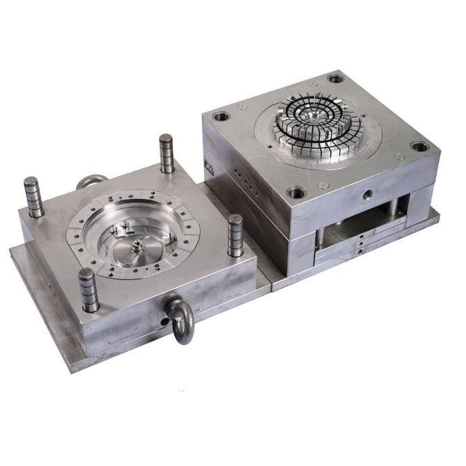
Step 6: Mold Assembly and Testing
Assembly Process
Assembling a mold requires precision and cleanliness:
- Clean all components: Any debris can cause defects or damage
- Install mold base: Fixed and movable plates with guide pillars and bushes
- Position cavities and cores: Secure with screws and dowel pins for precise alignment
- Assemble gating and runner systems: Ensure smooth connections
- Install ejection system: Ejector pins, plates, return pins
Guide pillars are critical—they ensure mold halves align perfectly. Misalignment causes uneven wall thickness or mold damage.
Testing and Debugging
Dry run: Close and open the mold without plastic. Observe moving parts—ejector pins, slides. Any sticking or binding must be corrected.
Initial molding trials: Run a small number of shots. Inspect parts for:
| Defect | Possible Cause |
|---|---|
| Short shots | Insufficient pressure; gate too small |
| Flash | Low clamping force; misalignment |
| Sink marks | Uneven cooling; excessive packing |
| Flow marks | Poor flow pattern; injection speed issues |
Adjust parameters or mold design based on results. Repeat until parts meet specifications.
Step 7: Maintenance and Optimization
Regular Maintenance
Proper maintenance extends mold life and prevents production interruptions.
| Task | Frequency | Purpose |
|---|---|---|
| Cleaning | After each run | Remove plastic residues, prevent buildup |
| Lubrication | Regularly | Reduce friction on guide pillars, ejector pins, slides |
| Inspection | Periodic | Check for wear, scratches, corrosion |
| Component replacement | As needed | Replace worn ejector pins, damaged seals |
A mold that receives regular maintenance can last 30% longer than a neglected one.
Optimization
Even after production starts, look for improvements:
- Cycle time reduction: Optimize cooling; add conformal cooling channels
- Quality improvements: Adjust process parameters; refine gate design
- Preventive replacements: Replace wear components before they fail
Conclusion
Designing and building an injection mold is a journey through seven essential steps:
- Product design and analysis – Understand the part and material
- Mold concept design – Plan parting line, cavities, and systems
- CAD modeling – Create precise 3D models
- Mold flow analysis – Simulate filling and optimize design
- Mold manufacturing – Machine with precision using CNC and EDM
- Assembly and testing – Build and validate the mold
- Maintenance and optimization – Extend life and improve performance
Each step builds on the previous. Skip one, and you risk defects, delays, and higher costs. Follow them all, and you’ll have a mold that produces consistent, high-quality parts for years.
FAQ
How long does it take to design and build an injection mold?
Lead times vary by complexity. Simple molds: 6–8 weeks. Complex molds with multiple cavities, slides, or tight tolerances: 10–14 weeks. Prototype molds using aluminum: 4–6 weeks.
What’s the most important step in mold design?
Mold flow analysis is often the most critical. It predicts how plastic will fill the cavity and identifies issues like air traps, weld lines, and short shots before steel is cut. Fixing these problems in the design phase saves significant time and cost.
How do I choose between steel and aluminum for my mold?
Steel is more durable and suited for high-volume production (100,000+ cycles). Aluminum costs less and machines faster but wears out sooner (10,000–50,000 cycles). For prototypes or low-volume production, aluminum is cost-effective. For high-volume production, steel is the better investment.
What causes sink marks on molded parts?
Sink marks are depressions on the surface, typically over thick sections. They occur when the outer layer solidifies while inner material continues to shrink. Solutions: reduce wall thickness, adjust packing pressure, or optimize cooling to ensure uniform solidification.
How often should I maintain my injection mold?
Inspect after each production run. Clean thoroughly. Lubricate moving parts regularly. For high-volume production, schedule deeper inspections every 10,000–50,000 cycles to check for wear, corrosion, and alignment issues. Preventive maintenance extends mold life significantly.
Contact Yigu Technology for Custom Manufacturing
At Yigu Technology, we specialize in precision injection mold design and manufacturing. Our team guides you through every step—from product analysis and DFM to mold flow simulation, CNC machining, and final testing.
We offer:
- In-house 5-axis CNC and EDM capabilities
- Mold flow analysis for defect prevention
- CMM inspection and full documentation
- Experience across automotive, medical, electronics, and consumer goods
[Contact Yigu Technology today] to discuss your injection mold project. Let’s build the tool that brings your product to life.