Introduction
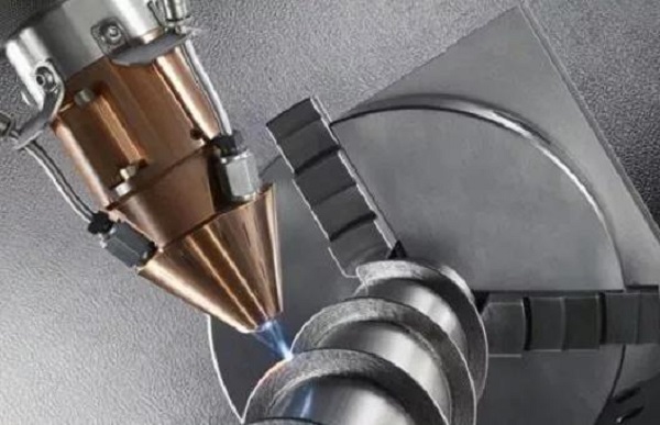
Speed matters in manufacturing. Faster production means lower costs, quicker market entry, and a sharper competitive edge. But fast machining is not simply running a spindle at higher speeds. It is a complete approach to material removal that changes how parts are made.
This strategy—often called High-Speed Machining (HSM) —combines high spindle speeds, rapid feed rates, and light cutting depths. The result is faster material removal, better surface finishes, and less stress on your tools and machines.
This guide explains what fast machining really means. You will learn how it differs from traditional methods, what technologies enable it, and how to apply it to your projects. We will share real examples and practical steps to help you get started.
What Defines Fast Machining?
Fast machining is not one single number. It is a system. The core elements are:
- High spindle speeds (often above 10,000 RPM)
- High feed rates (sometimes exceeding 1,000 inches per minute)
- Light depths of cut (small amounts of material per pass)
The goal is higher material removal rates (MRR) while improving surface finish. But here is the key science: when cutting speed increases, the heat from cutting goes into the chip, not the workpiece or tool. This keeps parts cooler, reduces thermal distortion, and extends tool life.
Think of it like shaving ice instead of chopping wood. Light, fast passes remove material efficiently without building up damaging heat.
How Does It Differ from Traditional Methods?
Traditional machining uses heavy cuts at slower speeds. This approach creates vibration, heat buildup, and high mechanical stress on parts and tools.
| Feature | Traditional Machining | Fast Machining (HSM) |
|---|---|---|
| Primary Strategy | Deep cuts, low speed/feed | Light cuts, very high speed/feed |
| Heat Management | Heat sinks into workpiece/tool | Heat evacuates with the chip |
| Cutting Forces | High radial forces | Lower radial forces, less vibration |
| Typical Application | Roughing, heavy stock removal | Finishing, complex contours, hard materials |
| Surface Finish | Often requires secondary finishing | Can achieve excellent finish directly |
Real example: A traditional method for a steel mold might use a 1/2-inch end mill taking a 0.150-inch depth of cut at 100 inches per minute. A fast machining approach for the same part might use a 1/4-inch end mill taking a 0.020-inch depth of cut at 800 inches per minute. The tool load drops dramatically. Overall throughput for finishing operations increases. And the surface finish improves.
What Technologies Enable High-Speed Cutting?
Fast machining requires more than a fast spindle. It needs an integrated system of technologies.
Machine Tool Design
The foundation is a rigid machine structure. Polymer-concrete or heavily ribbed cast iron absorbs vibrations. The machine needs:
- High-speed spindles (20,000–60,000 RPM common for HSM)
- Precise cooling and lubrication for the spindle
- Ultra-fast servo drives on linear axes for rapid direction changes
CNC Controller and Look-Ahead
This is where intelligence lives. The CNC must have look-ahead processing—sometimes analyzing over 1,000 program blocks ahead. It anticipates sharp corners and complex paths. It adjusts feed rates dynamically to maintain accuracy and prevent jerky motion that damages tools.
Tooling
Standard tool holders will not work. You need balanced toolholders like HSK or shrink-fit. These minimize runout at high RPM. Cutting tools require advanced materials:
- Micro-grain carbide
- Silicon nitride ceramics
- Coatings like Titanium Aluminum Nitride (TiAlN)
These materials withstand the thermal and mechanical shocks of high-speed cutting.
CAM Software
The programming backbone must generate smooth, flowing toolpaths. Constant engagement angles are critical. Two key strategies are:
- Trochoidal milling: The tool moves in circular arcs, maintaining constant tool engagement
- Adaptive clearing: The tool avoids full-width cuts that generate excessive heat
Real insight: A customer brought us a complex aerospace bracket. Traditional CAM programming took 8 hours of machining time. Using adaptive clearing toolpaths, we reduced that to 3.5 hours. Tool life increased by 40% because the tool never saw a full-width cut.
Which Materials Are Suitable for Fast Machining?
Fast machining works across many materials. But parameters change drastically for each type.
Non-Ferrous Metals (Aluminum, Copper, Brass)
These are the classic candidates. High-speed spindles excel here. You can achieve extremely high feed rates and mirror-like finishes. Machining aluminum aerospace components at 25,000 RPM and 500+ inches per minute is standard practice.
Steels and Cast Iron
Successful HSM in steels typically operates at 8,000–20,000 RPM. It is particularly beneficial for die and mold machining. You can machine hardened steels (up to 45–55 HRC) and drastically reduce hand polishing time.
High-Temperature Alloys (Inconel, Titanium)
Here, the goal is not ultra-high RPM. Instead, you use the HSM principle of light, fast cuts to manage heat. Keep chip load light and feed high. Heat pulls into the chip, preventing work hardening. Tool life extends significantly compared to conventional methods.
Real case: A medical implant manufacturer struggled with titanium parts. Conventional machining caused work hardening and short tool life. We switched to HSM parameters: light radial engagement, high feed rates, and through-spindle coolant. Tool life increased from 45 minutes to over 3 hours per tool. Cycle time dropped by 35%.
Composites and Plastics
Fast machining with sharp, specialized tool geometry prevents delamination in composites and melting in thermoplastics. The high speed provides a clean shear cut rather than tearing the material.
How to Optimize Feed Rates?
Optimization is the heart of fast machining. It is a balancing act between spindle speed, feed per tooth, and cutting depths.
Step 1: Start with Manufacturer Data
Consult cutting tool supplier charts. Look for recommended surface feet per minute (SFM) and chip load (feed per tooth) for your specific material and tool.
Step 2: Calculate Baseline Parameters
Use these formulas:
RPM = (SFM × 3.82) ÷ Tool Diameter
Feed Rate (IPM) = RPM × Number of Flutes × Chip Load
Step 3: Adopt Adaptive Strategies
For roughing, use adaptive toolpaths in your CAM software. These maintain a constant tool engagement—typically 10–15% of tool diameter. This allows you to safely increase the programmed feed rate by 150–300% without overloading the tool.
Step 4: Implement High-Efficiency Milling (HEM)
HEM is a subset of HSM focused on roughing. Use:
- Larger radial step-overs (up to 15% of tool diameter)
- Very light axial cuts (5–10% of tool diameter)
- High feed rates
This spreads wear evenly along the tool's cutting edge, extending tool life.
Step 5: Test, Monitor, and Refine
Start at 70–80% of your calculated maximum feed. Use spindle load monitoring. Listen to the cut:
- A consistent, high-frequency "hiss" is good
- A low-frequency "growl" or chatter indicates a problem
What Are the Key Benefits?
When implemented correctly, fast machining delivers transformative results.
| Benefit | Impact |
|---|---|
| Reduced Cycle Times | Especially for finishing and complex 3D contouring—MRR increases significantly |
| Superior Surface Quality | Often eliminates secondary polishing or grinding entirely |
| Reduced Machine Wear | Lower radial forces mean less stress on spindle bearings and machine structure |
| Extended Tool Life | Favorable heat transfer keeps cutting edges cooler |
| Thin Wall Capability | Minimal cutting force allows machining of fragile features that would deflect under traditional loads |
| Improved Accuracy | Less tool pressure and better heat management means tighter geometric tolerances |
Industry data: According to a 2025 manufacturing survey, shops implementing HSM strategies reported average cycle time reductions of 40–60% for finishing operations and tool life improvements of 20–50% across common materials.
Applications in Modern Manufacturing
Aerospace
Machining complex, integrated structural components from aluminum billets and titanium forgings. HSM enables the thin walls and deep pockets common in aircraft parts.
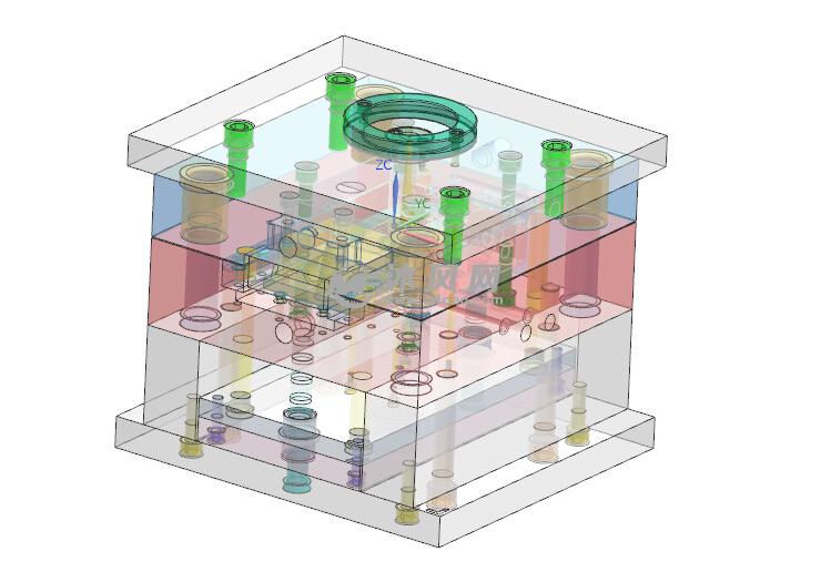
Die and Mold Making
This is the quintessential HSM application. Direct machining of hardened steel molds with near-net-shape accuracy slashes lead times from weeks to days. Hand polishing time drops by 70–80%.
Medical Device Manufacturing
Producing intricate, high-tolerance components from titanium (implants) and specialized plastics (surgical instruments). The low cutting forces prevent distortion in delicate parts.
Automotive and Electronics
Creating prototype parts rapidly. Producing high-volume precision components like engine blocks, transmission housings, and semiconductor fixture plates.
Conclusion
Fast machining is not a simple "turn up the speed" solution. It is a holistic integration of machine capability, intelligent programming, and process knowledge.
The core principles are clear:
- Use high spindle speeds with light cutting depths
- Let the chip carry away heat, not the workpiece
- Apply adaptive toolpaths to maintain constant tool engagement
- Match tools and parameters to your specific material
When you understand these principles, you unlock new levels of productivity, quality, and capability. In a market that demands both speed and precision, fast machining gives you a clear competitive advantage.
FAQ
Q: Is fast machining only suitable for finishing operations?
A: No. While extremely effective for finishing, the principles also apply to roughing through strategies like High-Efficiency Milling (HEM). HEM uses light axial depths and high feed rates to remove material quickly while preserving tool and machine health.
Q: Does fast machining require special coolant?
A: Not always. Many fast machining operations use Minimum Quantity Lubrication (MQL) or even compressed air for non-ferrous metals. For hard materials, high-pressure through-spindle coolant is often critical to break the chip and evacuate heat from the cut zone.
Q: Can my older CNC machine be used for fast machining?
A: It depends. The machine needs a sufficiently high-speed spindle, a fast controller with look-ahead, and excellent rigidity. Retrofitting an old machine for true HSM is often less economical than investing in a dedicated HSM center. However, some fast machining principles—like lighter depths of cut and optimized feeds—can improve performance on many machines.
Q: Is tooling cost much higher for HSM?
A: Initial tooling investment is higher. It requires precision-balanced holders and premium-grade carbide tools. However, due to extended tool life and dramatic cycle time reductions, the cost per part is typically lower. The upfront expenditure pays for itself quickly.
Q: What spindle speed is considered "high-speed" machining?
A: There is no single threshold, but HSM typically operates above 10,000 RPM for most materials. For aluminum and non-ferrous metals, speeds of 20,000–40,000 RPM are common. For steels, 8,000–20,000 RPM is typical depending on hardness.
Contact Yigu Technology for Custom Manufacturing
At Yigu Technology, we view fast machining as a core component of our intelligent manufacturing philosophy. We integrate state-of-the-art high-speed machining centers with advanced in-process monitoring and adaptive control systems.
Our capabilities include:
- High-speed CNC machining with spindles up to 30,000 RPM
- Adaptive toolpath programming for maximum efficiency
- Through-spindle coolant for difficult materials
- Real-time process monitoring to optimize parameters on the fly
- Expertise in challenging materials: titanium, Inconel, hardened steels, composites
We specialize in projects with complex geometries, difficult-to-machine materials, and stringent lead-time requirements. Whether you need prototypes for aerospace or production runs for medical devices, our fast machining capabilities ensure the perfect balance of quality, performance, and speed.
Our engineers work with you from design review to final delivery. We help optimize your parts for manufacturability, select the right tools and parameters, and deliver components that meet your exact specifications.
Contact Yigu Technology today for a custom quotation and engineering review. Let us show you how fast machining can transform your next project.