Insert molding is a sophisticated, value-driven manufacturing process that seamlessly combines metal, ceramic, or pre-molded plastic inserts with a thermoplastic substrate in a single molding cycle. This technique is fundamental for creating strong, multi-material, and fully integrated components that would otherwise require costly and less reliable secondary assembly. This comprehensive guide is crafted for product designers, manufacturing engineers, and procurement professionals seeking to leverage insert molding for enhanced product performance, reduced part counts, and improved assembly efficiency. We will dissect the process from first principles to advanced application, providing the actionable knowledge needed to design, specify, and manufacture superior insert-molded parts.
What Is Insert Molding?
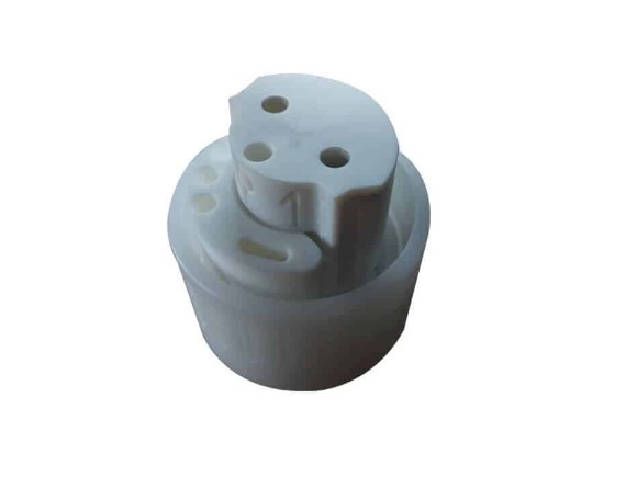
Insert molding is a specialized variant of injection molding where a pre-fabricated insert—such as a metal threaded boss, an electrical contact, a ceramic sensor, or even a printed circuit board (PCB)—is precisely placed into an injection mold. Molten plastic is then injected into the mold, flowing around and bonding to the insert. Upon cooling and ejection, the result is a single, cohesive molded assembly.
The core value proposition of insert molding lies in its ability to create strong, permanent bonds between dissimilar materials, eliminate post-molding assembly steps like press-fitting or ultrasonic welding, and enhance overall part reliability by reducing failure points associated with fasteners or adhesives.
How Does the Insert Molding Process Work?
The insert molding workflow is a precise, often automated sequence demanding meticulous planning. Deviations can lead to poor bonding, insert displacement, or mold damage.
- Insert Preparation & Feeding: Inserts are manufactured (e.g., stamped, machined) and prepared. This may include cleaning to remove oils or applying a surface treatment to enhance bond strength. For high-volume production, inserts are often fed via automated systems like bowl feeders or robotic pick-and-place units to ensure consistency and cycle time efficiency.
- Insert Placement: The prepared insert is accurately positioned into the designated cavity of the injection mold. Precision is paramount; inserts are typically held in place by retaining pins, magnetic fixtures, or a slight interference fit within the mold.
- Mold Closure & Injection: The mold closes, securing the insert. Molten thermoplastic is then injected under high pressure. The plastic flows around the insert, encapsulating it partially or fully. The injection parameters (temperature, pressure, speed) are critically tuned for the specific material pair.
- Cooling & Solidification: The assembly cools within the mold. Differential shrinkage rates between the insert and the plastic must be managed to prevent stress cracking or warpage.
- Ejection & Inspection: The mold opens, and the finished, encapsulated part is ejected. A 100% visual inspection is standard, often followed by statistical checks for bond integrity and dimensional accuracy.
Which Materials Are Best for Inserts and Substrates?
Success in insert molding hinges on the compatibility of the insert material with the thermoplastic substrate. The selection is driven by functional requirements and the need for a reliable mechanical or chemical bond.
| Component | Common Material Choices | Key Considerations |
|---|---|---|
| Inserts | Brass, Steel, Stainless Steel: For threaded fasteners, bushings, and structural reinforcements. | Thermal expansion coefficient vs. plastic. Surface treatments (knurl, groove, plating) for mechanical interlock. |
| Aluminum: For lightweight conductive parts or heat sinks. | Softer than steel; careful handling to prevent deformation during placement. | |
| Ceramics & Glass: For electrical insulation or optical elements in sensors. | Brittle; requires gentle handling and mold design to prevent cracking from clamp force or injection pressure. | |
| Pre-Molded Plastics & PCBAs: For creating overmolded grips or fully encapsulated electronics. | Must withstand molding temperatures; for PCBAs, thermal profiling is critical to avoid damage to components. | |
| Thermoplastic Substrates | ABS, Nylon (PA6, PA66), Polycarbonate (PC): Excellent general-purpose engineering plastics with good adhesion to treated metals. | Good mechanical strength and thermal resistance for demanding applications. |
| PBT, PPS: For high-temperature or harsh chemical environments (e.g., under-hood automotive). | High melt temperature; requires inserts that can withstand the heat without degrading. | |
| Thermoplastic Elastomers (TPEs): For soft-touch overmolding on rigid inserts. | Lower melt temperature; bonds via mechanical interlock on textured inserts rather than chemical adhesion. |
What Design Considerations Are Critical?
Poor design is the primary cause of failure in insert molded parts. Adhering to key design principles is non-negotiable.
- Insert Design for Retention: The insert must be designed to resist rotation and pull-out forces. This is achieved through mechanical interlocks such as knurling, grooves, holes, undercuts, or a hexagonal/flatted shape. A smooth, polished metal shaft will almost certainly fail.
- Boss and Wall Section Design: The plastic housing the insert must be sufficiently robust. A general rule is that the minimum plastic wall thickness surrounding an insert should be at least half the insert's diameter, and never less than 1.5mm. Inadequate thickness leads to stress cracking due to differential shrinkage.
- Draft and Radii: Incorporate draft angles (typically 1-2°) on plastic walls for easy ejection. All internal corners must have generous radii (min. 0.5mm) to facilitate plastic flow and reduce stress concentration points that can initiate cracks.
- Tolerance and Placement: The mold must locate the insert with precision. Design for a locating clearance of 0.002-0.005 inches per side between the insert and its mold pocket to allow for thermal expansion and easy placement, while preventing flash.
- Gate Location: The injection gate should be positioned to ensure uniform flow of plastic around the insert, avoiding weld lines over critical bonding surfaces and preventing asymmetric pressure that could displace the insert.
Engineering Case Study: A manufacturer was producing a handheld medical device with a stainless-steel blade insert molded into a polycarbonate handle. Initial designs used a smooth, cylindrical insert, resulting in a 15% field failure rate due to rotational slippage. The engineering team redesigned the insert with a deep, cross-hatched knurl pattern and added two transverse through-holes in its center. The molten PC flowed through these holes, creating robust "plastic rivets." This redesign increased the torsional retention strength by over 400% and eliminated field failures, with the added benefit of providing a visual quality check point.
Key Equipment and Tooling Requirements
Insert molding pushes standard injection molding equipment to require more specialized features.
- Injection Molding Machine: Must have precise shot control and often a programmable insert pick-and-place interface. Machines with a vertical clamp unit are frequently preferred for easier manual or robotic insert loading.
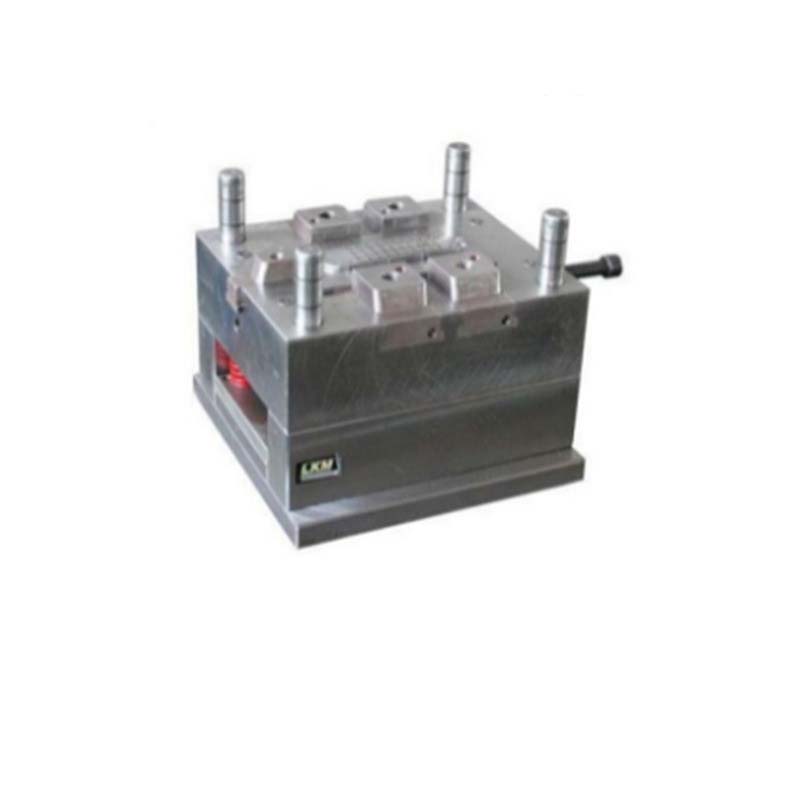
- Mold Design: The mold is the heart of the process. It requires:
- Precision Insert Cavities/Pockets: Machined to tight tolerances to securely locate the insert.
- Insert Retention Features: Spring-loaded pins, lifters, or magnets to hold the insert in place during mold closure.
- Robust Cooling Channels: Critical to manage the heat sink effect of metal inserts, which can cause localized slow cooling and part warpage.
- Automation: For volumes over 50,000 parts, automation is essential. This includes vibratory bowl feeders, vision-guided robots for precise placement, and integrated sensors to verify insert presence before each cycle, preventing costly mold damage.
How to Ensure Optimal Adhesion and Bond Strength?
Achieving a durable bond is a science that combines physics and chemistry.
- Mechanical Interlock (Primary Method): This is the most reliable bond. Design the insert with knurls, grooves, undercuts, or perforations. As the plastic shrinks onto these features during cooling, it creates a powerful physical lock. The bond strength can be calculated based on the shear area of the plastic engaged with these features.
- Thermal Bonding: The molten plastic must be hot enough to slightly elevate the surface temperature of the insert, allowing for intimate contact. For certain plastics like nylon, this can promote minor surface melting and fusion.
- Chemical Adhesion (Limited Use): Some material pairs, like polypropylene to untreated metal, have inherently poor adhesion. In these cases, a bonding agent or a specialized coating on the insert may be used. However, this adds cost and process complexity and is generally avoided in favor of a robust mechanical design.
- Process Control: Mold temperature and injection speed are critical. A hotter mold allows the plastic to remain fluid longer, improving flow around intricate insert features. A faster injection speed can improve surface wetting of the insert.
Cost Factors and Production Efficiency
While insert molding adds cost compared to standard molding, it often creates net savings at the assembly level.
Cost Drivers:
- Insert Cost: The unit cost of the fabricated metal/ceramic insert.
- Tooling Complexity: Molds are more complex due to insert placement features, often costing 20-35% more than a comparable standard mold.
- Cycle Time: The process is slower. Manual insert placement can add 5-15 seconds per cycle. Automated placement is faster but adds capital expense.
- Yield & Scrap Risk: A misplaced or missing insert can lead to a defective part and potential mold damage, impacting overall yield.
Efficiency & Value Gains:
- Eliminated Assembly: Removes the cost of secondary operations (staking, screwing, adhesive bonding, ultrasonic welding) and their associated labor, fixtures, and floor space.
- Enhanced Reliability: A single, monolithic part has fewer potential failure points than a multi-part assembly, reducing warranty claims and improving product lifespan.
- Part Consolidation: Can combine multiple components into one, simplifying the Bill of Materials (BOM) and supply chain.
Applications Across Automotive, Medical, and Consumer Electronics
Insert molding solves critical design challenges across high-stakes industries.
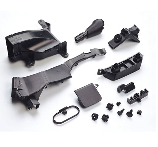
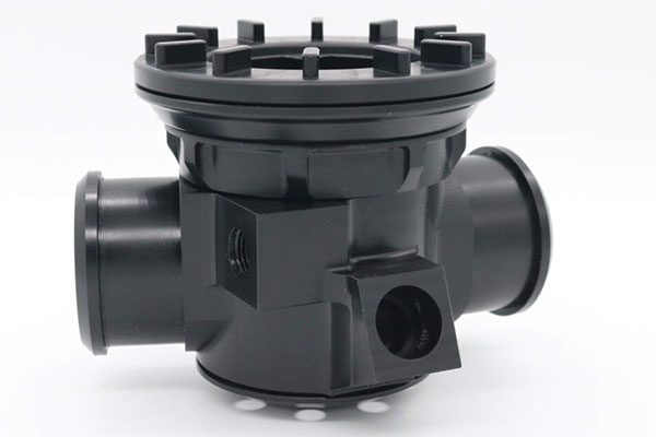
- Automotive: Used for electrical connectors (pins molded into housings), gear shift knobs (metal core for weight/feel, plastic exterior), and sensor housings where a brass fitting is integrated for fluid connections. It provides vibration resistance and long-term seal integrity.
- Medical: Essential for single-use surgical instruments (metal blades or razors molded into plastic handles), connectors for IV sets, and diagnostic sensor housings. It creates clean, sealed interfaces without crevices that could harbor bacteria.
- Consumer Electronics: Ubiquitous in power tool housings (for metal reinforcement in stress areas), wearable device chassis (for embedded nuts or antenna elements), and USB connector assemblies. It enables robust, miniaturized designs.
Industry Trend: The rise of molded interconnect devices (MIDs) is a direct extension of insert molding. Here, a patterned circuit is created on a 3D plastic part, often by laser direct structuring (LDS) or two-shot molding with a plateable resin. This allows for the full integration of mechanical and electronic functions, such as an antenna molded directly into a smartphone case.
Conclusion
Insert molding is a powerful enabler of product innovation, offering unparalleled benefits in part strength, functional integration, and assembly simplification. Its successful implementation is not a matter of chance but of rigorous engineering—from the fundamental design of the insert's retention features to the precise control of the molding process. By understanding the material compatibilities, critical design rules, and cost-performance trade-offs outlined in this guide, engineers and designers can confidently specify insert molding to create more reliable, cost-effective, and high-performance products that stand out in the market.
FAQ
What is the difference between insert molding and overmolding?
Insert molding typically refers to encapsulating a rigid, pre-formed metal or ceramic insert with plastic in a single shot. Overmolding generally involves molding a layer of a second material (often a soft TPE) over a first molded plastic substrate, which can be done in a two-shot process or via insert molding of a pre-molded part. The key distinction is that insert molding often combines dissimilar material families (metal+plastic), while overmolding often combines compatible plastics.
Can standard injection molding machines be used for insert molding?
Yes, most standard machines can be adapted for insert molding. However, for optimal efficiency and quality, features like vertical clamps, programmable logic controller (PLC) integration for robotics, and precision shot control are highly beneficial. The mold, not the machine, is the primary differentiator.
How are inserts held in place inside the mold before injection?
Inserts are secured using various methods: Interference Fit (slight press-fit into the mold), Retaining Pins (spring-loaded pins that retract upon mold closure), Magnetic Holders (for ferrous metal inserts), or Vacuum Channels. The method is chosen based on insert size, shape, and production volume.
What are the most common failure modes in insert molded parts?
The top failures are: Insert Pull-Out/Rotation (insufficient mechanical interlock or poor adhesion), Stress Cracking in the plastic around the insert (due to high differential shrinkage and poor wall design), and Insert Displacement/Flash during injection (due to poor fit in the mold pocket or excessive injection pressure).
Is insert molding suitable for low-volume production or prototyping?
It can be, but the economics are challenging. For prototyping, manual insert placement in a low-cost aluminum mold is common. For low volumes, the high cost of the insert and the slower cycle time must be justified by the functional necessity of the part. Alternative assembly methods should be evaluated for runs under a few thousand pieces.
Contact Yigu Technology for Custom Manufacturing.
Unlock the potential of integrated, high-strength components with Yigu Technology's expert insert molding services. Our engineering team specializes in Design for Manufacturability (DFM) analysis for complex insert applications, ensuring optimal bond strength and reliability from the start. We possess the specialized tooling expertise, precision automation, and materials knowledge to manage the unique challenges of combining metals, ceramics, and plastics. From automotive sensors to life-saving medical devices, we deliver robust, cost-effective solutions that consolidate parts and enhance performance. Contact Yigu Technology today to discuss your project and leverage our expertise for your next innovative product.