Introduction
You have a great product idea. You have spent hours perfecting the digital design. But how do you know it will work in the real world? That gap between the screen and physical reality is where products succeed or fail.
A CNC model bridges that gap. It transforms your CAD file into a tangible object made from real engineering materials. Unlike basic prototypes, these models offer production-grade accuracy, material integrity, and superior surface finish. They serve as the final proof before mass production.
This guide walks you through everything about CNC models. You will learn what they are, how to optimize your designs for machining, and what post-processing steps turn a raw part into a polished model. By the end, you will have a clear path to using CNC models for flawless product development.
What Is a CNC Model?
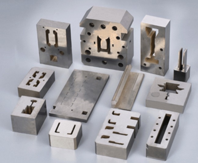
A CNC model is a physical part machined from a solid block of material. The process uses Computer Numerical Control (CNC) technology. Your digital 3D model—usually a CAD file—guides cutting tools to remove material with exceptional precision.
The result is a high-fidelity part that you can:
- Test functionally under real conditions
- Check fit with existing assemblies
- Present as a high-end sales sample
Think of it as your design, made real, with the exact properties of the final production part.
How Do CNC Models Differ from Traditional Prototypes?
Not all prototypes are equal. CNC models occupy a unique space. Here is how they compare to common 3D printing methods like FDM or SLA.
| Feature | CNC Model | 3D Printed Prototype |
|---|---|---|
| Process | Subtractive (removing material) | Additive (building layers) |
| Material | Real, isotropic engineering materials | Plastic polymers, resins (often anisotropic) |
| Accuracy | Very high (±0.025 mm typical) | Moderate to good (±0.1–0.5 mm typical) |
| Strength | Equal to final production material | Material-dependent, often lower |
| Best For | Functional testing, fit checks, high-end visuals | Form studies, complex geometries, rapid iteration |
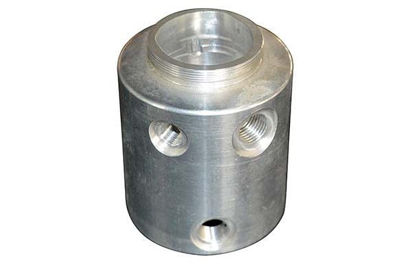
Key difference: A CNC-machined aluminum housing has the same thermal conductivity, strength, and feel as the final production part. A 3D-printed version cannot match that.
Which Software Creates the Most Accurate CNC Models?
Accuracy starts with your digital model. The right software depends on your industry and part complexity.
Engineering and Mechanical Design
SolidWorks, Autodesk Inventor, and Siemens NX lead this space. They create parametric, feature-based models with precise constraints. Their strength is modeling manufacturable parts with clear design intent. This makes the translation to CNC toolpaths logical and error-free.
Complex Surfacing and Automotive/Aerospace
CATIA and Creo (formerly Pro/ENGINEER) dominate here. They excel at Class-A surfacing and managing complex assemblies. For aerodynamic or ergonomic forms where surface continuity is critical, these tools provide unparalleled control.
Aesthetic and Organic Design
Rhino 3D, especially with its Grasshopper plugin, shines for free-form, organic shapes. It is common in architecture, jewelry, and consumer product design. Its NURBS-based modeling ensures smooth, accurate surfaces.
What Materials Work Best for CNC Model Making?
Material choice drives the model's purpose: form, fit, or function.
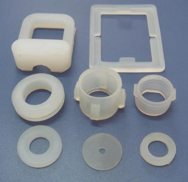
For Visual and Fit Models (Non-Functional)
| Material | Best For |
|---|---|
| Machinable Wax | Intricate details, mold patterns |
| Urethane Boards | Fine features, plastic-like finish |
| PU Boards (Tufnol, Duraplex) | Simulating ABS or polypropylene |
These materials are soft and machine easily. They produce fine details without high tool wear.
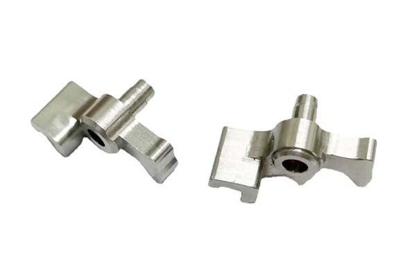
For Functional and Load-Bearing Models
| Material | Properties | Applications |
|---|---|---|
| Aluminum (6061, 7075) | Excellent strength-to-weight, good machinability | Enclosures, brackets, mechanical parts |
| POM (Delrin) | High stiffness, low friction, dimensional stability | Gears, bearings, sliding parts |
| Stainless Steel (304, 316) | Corrosion resistance, high strength, high-temperature performance | Testing under harsh conditions |
Real insight: A client once needed a functional test for a medical device bracket. We machined it from 316 stainless steel—the exact production material. The test revealed a stress point that plastic prototyping had missed. That discovery saved them thousands in potential recalls.
How to Optimize CAD Data for CNC Model Production?
A perfect-looking CAD model does not always mean a manufacturable part. Optimization matters.
Ensure Watertight Geometry
Your model must be a single, cohesive solid. No gaps, overlaps, or stray edges. Use the "Check Entity" or "Validation" tools in your CAD software to verify.
Define Clear Tolerances
Apply geometric dimensioning and tolerancing (GD&T) in your drawing or model properties. This guides the machinist on what features are critical. Ambiguity leads to guesswork.
Consider Tool Access
Design with realistic tool diameters in mind. An internal sharp corner with a 1 mm radius requires a tool no larger than 2 mm in diameter. If your design has a 0.5 mm internal corner, you may need specialized micro-tools.
Simplify Where Possible
Remove unnecessary cosmetic textures, decals, or extremely fine details that fall below the CNC tool's capability. These can be added later through etching or laser marking.
Export in a Neutral Format
While native CAD files (like .SLDPRT) are best, a STEP (.stp) or Parasolid (.x_t) file is the most reliable neutral format. It transfers geometry between different CAM software without data loss.
What Scaling Challenges Arise in CNC Model Machining?
Scale models—like a 1:10 architectural model—bring unique hurdles.
Feature Resolution
Small-scale details can become smaller than the minimum tool diameter. A window frame detail that is 20 mm wide at full scale becomes only 2 mm at 1:10 scale. This may require specialized micro-tools.
Tool Deflection and Breakage
At reduced scales, forces on tiny tools are proportionally high. This leads to deflection (reducing accuracy) or breakage. Machining strategies must use lighter cuts and higher spindle speeds.
Material Grain and Texture
The inherent grain of materials like wood or the texture of foam boards can become disproportionately large on a small model. This ruins the aesthetic.
Real case: An architectural firm needed a 1:50 scale model of a complex facade. The specified timber would have shown grain patterns that overwhelmed the fine details. We switched to a fine-grained modeling board (PU foam). We used a 0.5 mm diameter ball-nose end mill with high-speed machining toolpaths. This captured delicate mullion details without tool failure.
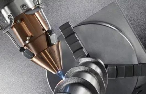
How to Achieve Fine Surface Details on a CNC Model?
Meticulous surface details require strategic machining and careful tool selection.
Toolpath Strategy
Start with a roughing pass using a larger tool to remove bulk material. Then use multiple finishing passes with progressively smaller tools. Contour-parallel or scallop-height finishing toolpaths provide consistent surface quality.
Tool Selection
- Ball-nose end mills are essential for 3D contours and organic shapes
- V-bit engraving tools for fine text or textures
- Micro end mills (down to 0.1 mm) for extremely fine details
Machine Rigidity and Speed
A high-precision, rigid CNC machine with a high-frequency spindle is necessary. You need to run tiny tools at high RPMs—often 20,000+ RPM—without vibration. Vibration causes chatter and ruins surface finish.
What Post-Processing Steps Refine a CNC Model?
The machined part is only the beginning. Post-processing turns it into a polished model.
Support Removal and Deburring
Carefully remove any tabs or support structures used during machining. Use hand files, scrapers, or sandpaper to remove all sharp edges (burrs). A part with burrs looks unfinished and can be unsafe to handle.
Sanding and Polishing
Begin with coarse grit sandpaper to remove tool marks. Move progressively to finer grits—up to 2000+ grit. For plastics and metals, mechanical polishing with compounds can achieve a mirror-like finish.
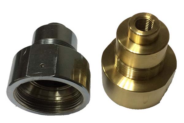
Priming and Painting
Apply a filler primer to reveal microscopic imperfections. Sand again. Then use model-specific paints applied in light, even coats. For metals, anodizing or powder coating provides a durable, professional finish.
Adding Final Details
Apply decals, labels, or cosmetic textures using pad printing or waterslide decals. For metallic logos, electroplating or physical vapor deposition (PVD) coating on specific areas adds a premium touch.
Real insight: A consumer electronics client needed presentation models for a product launch. The raw machined aluminum parts were functional but looked industrial. We applied a bead-blasted finish followed by clear anodizing. The result? Parts that looked production-ready. The client closed funding with those models.
Conclusion
A CNC model is more than a prototype. It is tangible validation of your design, engineering, and manufacturability. By understanding the entire ecosystem—from CAD software and material selection to geometry optimization and post-processing—you can de-risk product development.
The right CNC model:
- Reveals fitment issues before tooling
- Confirms material behavior under real conditions
- Impresses stakeholders with production-grade quality
- Paves a smoother path to mass production
In a world of digital design, the physical truth offered by a precision CNC model remains indispensable.
FAQ
What file format is best for CNC machining?
Native CAD files like .SLDPRT or .IPT are ideal. For neutral transfer, STEP (.stp) and Parasolid (.x_t) are the most universally accepted formats that preserve solid geometry accurately.
Can a CNC model be made from the same material as mass production?
Yes. This is one of the primary advantages. You can machine the model from the exact aluminum, steel, or plastic specified for production. This ensures identical mechanical and thermal properties for testing.
How expensive is a CNC model compared to a 3D-printed one?
Cost depends on size, material, and complexity. For simple, small parts, 3D printing is often cheaper. For larger, dense parts or those requiring engineering materials and tight tolerances, CNC can be comparable or even more cost-effective—especially when material properties matter.
What is the typical lead time for a CNC model?
Lead time varies. Simple models may take 2–5 days. Highly complex, large, or finely finished pieces can take 2–3 weeks. This includes CAD preparation, CAM programming, machining, and post-processing.
How tight of tolerances can CNC models achieve?
Precision CNC machining achieves tolerances as tight as ±0.025 mm or better. This is essential for components that must mate perfectly with existing assemblies or meet strict functional requirements.
Contact Yigu Technology for Custom Manufacturing
At Yigu Technology, we view the CNC model as the cornerstone of successful manufacturing. It is the final, unforgiving test of design integrity. Our experience shows that investing in a high-fidelity CNC prototype saves substantial time and cost downstream. It exposes fitment issues, material behavior, and machining challenges early—when changes are still inexpensive.
We combine state-of-the-art 5-axis CNC capabilities with deep engineering expertise. We do not just machine your model. We collaborate to optimize your design for manufacturability (DFM). Our team helps you select the right materials, refine geometry for tool access, and achieve the surface finish your project demands.
Whether you need functional test parts, fit-check models, or high-end presentation samples, we deliver precision you can trust.
Contact us today to discuss your next project. Let us help transform your digital vision into a perfect physical reality.