Introduction
You have a great product idea. You can picture it in your mind. But how do you turn that vision into something real? The answer starts with a CAD model.
A CAD (Computer-Aided Design) model is the digital blueprint of your product. It holds every dimension, every curve, and every critical detail. More than just a drawing, it contains geometric data, material properties, and manufacturing information. It is the foundation that connects your idea to production.
This guide walks you through the entire CAD design process. You will learn why CAD models matter, what software to choose, and how to create models that are accurate, manufacturable, and ready for production. Whether you are new to CAD or looking to refine your skills, this guide gives you a clear path forward.
What Is a CAD Model?
A CAD model is a digital representation of a physical object or system. It is created using specialized CAD software. Models can be two-dimensional or three-dimensional, depending on your project needs.
2D CAD Models
2D CAD models create precise technical drawings. These include:
- Floor plans and blueprints
- Mechanical part diagrams
- Electrical schematics
In architectural design, 2D CAD models show room layouts, wall positions, and door placements. They work well when a detailed view of a single plane is sufficient.
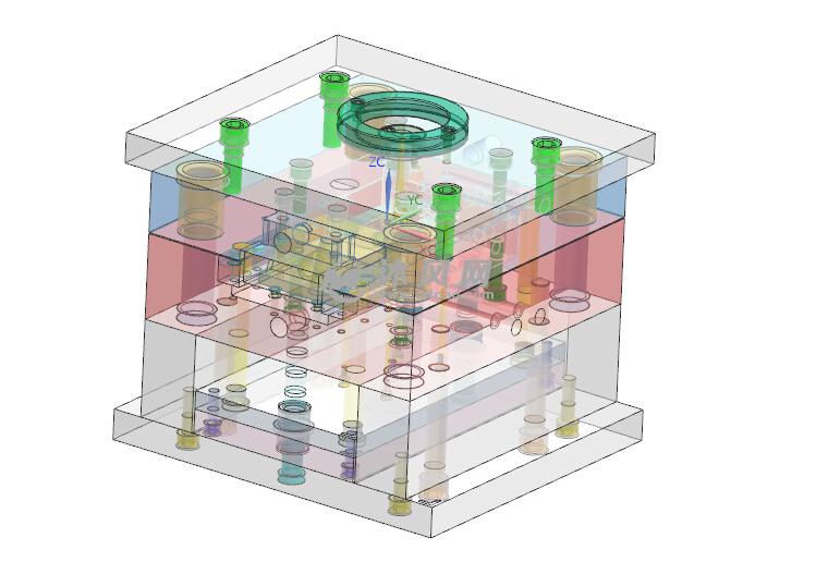
3D CAD Models
3D CAD models add depth. They allow realistic visualization from all angles. These models are used across industries:
- Automotive: Car body shapes, interior components
- Aerospace: Aircraft structures, engine parts
- Product design: Consumer electronics, appliances
A 3D CAD model is not just a pretty picture. It contains geometric data (dimensions, shapes, positions), material properties, and sometimes manufacturing process information. This makes it an essential tool for modern engineering.
Why Design a CAD Model?
The advantages of CAD design have transformed manufacturing. Here is why it matters.
Enhanced Design Precision
CAD software allows exact measurements and specifications. Human error common in manual drafting is minimized.
In microchip design, the smallest deviation can cause failure. CAD models ensure every circuit is placed with extreme accuracy. Complex shapes and geometries that would be impossible by hand become achievable.
Accelerated Design Process
Changes happen fast. Instead of redrawing an entire design, you adjust parameters and the model updates instantly.
In smartphone development, designers experiment with shapes, sizes, and button placements within hours. Multiple concepts are explored before finalizing one. What once took weeks now takes days.
Cost Reduction
Finding flaws in the virtual model saves real money. Errors caught before production avoid costly rework.
In aircraft construction, a design error discovered after production starts can cost millions. CAD models detect issues like component interference early, ensuring fewer errors and lower costs.
Improved Visualization and Communication
A 3D CAD model shows exactly what the final product will look like. Designers can view from any angle, zoom in on details, and create animations showing function.
For clients, this clarity means better feedback and faster approvals. An interior designer can show a client exactly how a redesigned living room will look—with furniture, lighting, and colors all represented.
Easier Collaboration
CAD models share easily across teams, regardless of location. Multiple designers, engineers, and stakeholders can work simultaneously on the same project.
In bridge design, civil engineers, structural engineers, and architects all contribute to one model. Everyone works toward the same goal with real-time updates.
Steps to Design a CAD Model
Step 1: Define the Requirements
Before opening any software, understand what you are building.
- Function: What does the product do?
- Use case: Where and how will it be used?
- Performance criteria: What loads, speeds, or conditions must it handle?
Real example: Designing a bicycle frame requires considering load-bearing capacity, riding type (mountain, road), and ergonomic requirements. A smartphone design must fit comfortably in a hand while accommodating battery, motherboard, and camera.
Material choice matters. Aerospace components use lightweight titanium or carbon fiber to reduce weight and increase fuel efficiency.
To gather requirements:
- Conduct market research
- Study similar products
- Communicate closely with clients or end-users
Step 2: Select the Right CAD Software
Choosing software is a key decision. Here are popular options.
| Software | Key Features | Best For | Approximate Annual Cost |
|---|---|---|---|
| AutoCAD | Industry-standard 2D drafting, basic 3D | Architecture, civil engineering, 2D plans | $1,775 |
| SolidWorks | Parametric 3D modeling, assembly design, interference checking | Mechanical engineering, product design | $4,195 |
| CATIA | High-end 3D modeling, complex surface modeling, advanced simulation | Aerospace, automotive, shipbuilding | $10,000+ |
Your choice depends on your needs, budget, and project complexity. For 2D architectural drawings, AutoCAD works well. For complex 3D mechanical designs, SolidWorks or CATIA are better suited.
Step 3: Create a Sketch
Sketching is where ideas take shape. This is your rough draft—a chance to explore concepts quickly.
Use basic drawing tools: lines, circles, rectangles, and arcs. Precision is not the goal yet. The goal is to get ideas on the digital canvas.
For a furniture piece, start with a simple 2D sketch to determine tabletop shape, leg positions, and proportions. This sketch becomes the foundation for detailed 3D modeling.
Step 4: Build the 3D Model
Now you convert your 2D sketch into a three-dimensional object. Several techniques are used.
| Technique | Description | Example |
|---|---|---|
| Extrusion | Adds depth to a 2D shape | A circle extruded becomes a cylinder |
| Revolution | Rotates a 2D profile around an axis | Creates shafts, vases, or round parts |
| Lofting | Connects multiple 2D cross-sections | Creates complex shapes like airplane bodies |
Pay attention to:
- Axis orientation
- Dimension accuracy
- Smooth transitions between model features
Use snap and grid features in your software to improve accuracy.
Step 5: Apply Materials and Textures
Materials and textures bring your model to life. Different materials have unique optical and physical properties.
Use material libraries in your CAD software. These contain:
- Metals (aluminum, steel, titanium)
- Plastics (ABS, polycarbonate, nylon)
- Wood and composites
Textures add realism. A wooden texture shows grain patterns. A metal texture shows reflectivity. Some software allows custom texture imports for even more control.
Step 6: Assemble and Check for Interference
If your design has multiple components, you must assemble them in CAD. This simulates how parts fit together in the real world.
Interference checking is critical. Interference occurs when two or more components occupy the same space.
Real case: In a recent robotic arm project, interference checking revealed that a newly added sensor was colliding with a moving joint. By modifying the sensor position in CAD, we eliminated the issue before physical production began.
Most CAD software has built-in interference checking tools. They quickly identify problem areas and show which components are involved.
Step 7: Analyze and Simulate
CAD software offers powerful analysis capabilities. You can test performance without building physical prototypes.
| Analysis Type | Purpose | Application |
|---|---|---|
| Structural Analysis | Determines response to loads | Bridge stress under traffic weight |
| Fluid Analysis | Optimizes fluid flow | Reducing pressure drops in pipes, aerodynamic drag on vehicles |
| Thermal Analysis | Predicts heat distribution | Electronic component cooling |
Based on simulation results, you optimize your design. If analysis shows high stress in one area, modify shape, thickness, or material to improve strength.
Step 8: Finalize and Document
Once the design is complete, documentation becomes essential.
Design Specification: Product function, performance requirements, materials used, and relevant standards.
Technical Drawings: Detailed 2D drawings with accurate dimensions, tolerances, and annotations. These guide manufacturers.
Bill of Materials (BOM): Lists every component with part numbers, descriptions, and quantities.
Proper documentation ensures everyone—from manufacturers to quality control—understands the requirements. It also serves as a reference for future modifications.
Conclusion
A CAD model is more than a digital drawing. It is the bridge between concept and reality. It holds the precision, the material choices, and the manufacturing knowledge that turns ideas into products.
By following a structured process—defining requirements, choosing the right software, building accurate models, and documenting thoroughly—you create designs that are not just visually appealing but manufacturable and reliable.
Good CAD design saves time, reduces costs, and prevents errors before they reach production. It is the foundation of modern manufacturing.
FAQ
What is the best CAD software for beginners?
Fusion 360 and Tinkercad are excellent for beginners. Fusion 360 offers an intuitive cloud-based platform with integrated CAD, CAM, and CAE tools. Autodesk provides extensive tutorials and a supportive community. Tinkercad is free and uses a drag-and-drop interface, making it accessible even with no prior CAD experience.
How can I improve the accuracy of my CAD model?
Start with precise drawing. Use snap and grid features to ensure lines and points are placed exactly. Set appropriate tolerances based on your design requirements. Regularly verify dimensions and geometric relationships using measurement and analysis tools in your software.
Can I use a CAD model for 3D printing?
Yes. You need to convert the model to STL (Stereolithography) format. Ensure your model is watertight and manifold—no holes or non-manifold geometry. Design support structures for overhanging parts to keep the model stable during printing.
What is the difference between parametric and direct modeling?
Parametric modeling uses parameters and constraints to define geometry. Changing a parameter updates the entire model. Direct modeling manipulates geometry freely without a history tree. Parametric is better for designs requiring frequent modifications. Direct is faster for simple or one-off models.
How do I ensure my CAD model is manufacturable?
Consider tool access. Avoid internal sharp corners smaller than available cutting tools. Use standard hole sizes and thread specifications. Apply realistic tolerances—tighter is not always better. Perform DFM (Design for Manufacturing) reviews early with your manufacturing partner.
Contact Yigu Technology for Custom Manufacturing
At Yigu Technology, we understand that a great CAD model is the foundation of great manufacturing. As a custom supplier of non-standard plastic and metal products, we work directly with your CAD data to produce precision components.
Our experience shows that a well-designed CAD model bridges design concept with actual production. We use your models to:
- Identify potential manufacturing issues early
- Optimize designs for cost and efficiency
- Transfer data directly to our manufacturing equipment
- Reduce manual measurements and interpretation errors
In a recent project involving a complex metal-plastic composite component, CAD-based interference checking revealed a design issue that would have caused injection molding problems. By modifying the CAD model, we ensured smooth production and high-quality results.
Contact us today to discuss your project. Let us help you turn your CAD model into a high-quality, manufacturable product.