Introduction: Why is Understanding CNC Lathe Components Crucial?
For machining practitioners, equipment maintenance personnel, or industry learners, understand parts of CNC lathe(CNC lathe components) structure, function and synergistic logic are the core prerequisites for improving machining accuracy, reducing the probability of failure, and optimizing production efficiency. Whether it is parameter adjustment when facing complex workpiece processing or quick troubleshooting in the event of a sudden failure of equipment, solid component knowledge can help you avoid detours. This article will break down the key components of CNC lathes in an all-round way, from the infrastructure to the core system to the actual application scenarios, so that you can use them after reading.
1. Core structure and functional system: the "skeleton" support of the lathe
The stable operation of CNC lathes relies first and foremost on a solid core structure. This part of the component is like the "skeleton" of the lathe, which determines the rigidity, stability and basic precision of the machine.
| Core components | Mounting location | Core features: | Key impacts |
| Headstock | lathe bed end | The drive spindle rotates at high speed and transmits power | The accuracy of the internal gear directly affects the stability of the spindle speed, which in turn affects the roughness of the machining surface |
| bed | Lathe bottom foundation | Carry all components, provide installation references | The material (mostly cast iron or granite) determines the rigidity, and the deformation should be controlled within 0.002mm |
| Rails | The top of the bed supports the skateboard | Guide the slide and tool holder to move precisely | The straightness error ≤ 0.01mm/m, and poor lubrication can easily lead to stuttering or wear |
| Spindle | Headstock core components | Clamp the workpiece and drive its rotation | The speed range is typically 0-3000rpm, and the radial runout is ≤ 0.003mm |
| Chuck | Spindle front end | Fast clamping of workpieces | Common three-jaw chucks have a centering accuracy of ±0.01mm, and the clamping force of hydraulic chucks can reach 50kN |
| tailstock | The end of the lathe bed | Support long workpieces or install drills and reamers | The coaxiality error with the spindle ≤ 0.02mm to ensure the accuracy of deep hole machining |
| Protective cover | Lathe exterior | Protect against debris splashing, sound insulation and dust prevention | Shockproof and IP54 rating |
Actual case: A precision parts processing factory once had an uneven load on the guide rail due to uneven bed installation, and the roundness error of the processed shaft parts exceeded 0.03mm, far exceeding the customer's requirement of 0.01mm. The problem was subsequently resolved by recalibrating the bed level and replacing the wear rail slides. This also confirms the decisive role of the core structure in machining accuracy.
2. Drive and motion system: the "power heart" of the lathe
If the core structure is the "skeleton", the drive and motion system is the "power heart" of the CNC lathe, which directly determines the speed, precision, and flexibility of machining.
1. Core drive components
- Servo motor: As a power source, it controls the movement of the feed shaft and spindle, with a response speed of ≤ 20ms and a positioning accuracy of up to ±0.001mm, which is the key to achieving precise control. At present, servo motors from mainstream brands such as Panasonic and Siemens can still maintain stable torque at high speeds.
- Ball screw: Connecting the servo motor and the skateboard, it converts rotational motion into linear motion, and the transmission efficiency is as high as 90%-98%, which is far better than ordinary trapezoidal screws (30%-40%). Its lead error ≤ 0.005mm/m, low wear, and a service life of more than 10000 hours.
2. Key moving parts
- Feed axis (X-axis, Z-axis): X-axis controls transverse cutting (turning diameter direction), Z-axis controls longitudinal feed (turning length direction), and the two-axis linkage can realize complex surface machining, with a repeat positioning accuracy ≤ 0.002mm.
- Tool holder: divided into turret tool holder (can install 8-12 tools, tool change time 0.3-1 seconds) and power tool holder (supports milling, drilling and other compound processing, the speed can reach 5000rpm), which is the core component to improve machining efficiency.
- Skateboard (cross skateboard): The carrying tool holder moves along the guide rail, with hardening treatment (hardness HRC58-62), with a rolling guide rail pair, with low movement resistance and strong rigidity, to ensure that no displacement occurs during the cutting process.
Professional analysis: The synergy between the drive and the motion system is crucial. For example, the response speed of the servo motor needs to be accurately matched with the lead of the ball screw, and if the parameters are not set properly, there will be a phenomenon of "lost step", resulting in deviation in the machining size. An auto parts factory once caused the Z-axis feed to be uneven, and the depth of the processed crankshaft keyway fluctuated by more than 0.02mm, and finally controlled the fluctuation within 0.005mm by adjusting the electronic gear ratio and optimizing the acceleration and deceleration time constant.
3. CNC Control System and Operating Unit: The "Brain Center" of the Lathe
The CNC control system is the "brain" of the lathe, responsible for receiving programming instructions, parsing signals, and controlling the components to work together, making it the core of automated machining.
| Control components | Core features: | Operational points |
| CNC Systems (CNC Controllers) | Parse G-code, M-code, and control motion trajectories | Mainstream systems such as FANUC 0i-TF and Siemens 828D support 3-5 axis linkage and have a user-friendly programming interface |
| Operation panel | Manually enter instructions, adjust parameters, start/stop machining | Including emergency stop button, handwheel, and coordinate axis selection key, the sensitivity of the button should be checked regularly |
| Display | Display of machining trajectory, parameters, and fault information | Most of them are 10-15-inch touch screens with a resolution ≥ 1024×768, ensuring a clear view of complex programs |
| Programming panel | Enter, edit, and store processing programs | Support USB flash drive import/export programs, with program verification function to avoid syntax errors |
| Servo drive | Amplify the servo motor control signal to adjust the speed and torque | It is necessary to match the servo motor model and calibrate the current and voltage parameters regularly |
Industry Data: According to statistics, approximately 60% of CNC lathe failures stem from improper control system settings or program errors. For example, a mold factory did not consider tool radius compensation during programming, resulting in a cavity size that was 0.1mm smaller, and then added compensation parameters to the CNC system to reprocess the size to meet the standard. It is recommended that operators regularly learn the system update function, familiarize themselves with advanced programming instructions, and improve control accuracy.
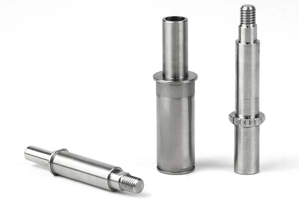
4. Tool and workholding system: "direct guarantee" of machining accuracy
The tool and the workholding system are in direct contact with the workpiece, and its performance and reasonable selection directly determine the processing quality and efficiency.
- Turning tools: according to the material, they are divided into carbide knives (strong wear resistance, suitable for high-speed cutting), high-speed steel knives (good toughness, suitable for low-speed finishing), and can be divided into external cylindrical knives, internal bore knives, threaded knives, etc. according to the use.
- Blade: As the cutting edge of turning tools, common materials include PCD (diamond, suitable for non-ferrous metal processing), CBN (cubic boron nitride, suitable for hardened steel processing), and the cutting edge accuracy ≤ 0.001mm.
- Tool holder: The connection between the blade and the tool holder should be rigid enough, and the clamping accuracy ≤ 0.002mm to avoid vibration during cutting.
- Turret: Cooperate with the tool holder to achieve quick tool switching, and the high-end turret supports tool life management function, which can automatically remind you to change blades.
2. Workholding components
- Chuck: In addition to the conventional three-jaw chuck, the hydraulic chuck has high clamping efficiency and uniform force, and is suitable for batch processing; The four-jaw chuck can clamp irregular workpieces with a centering accuracy of ±0.005mm.
- Tip: It is divided into fixed tip (good rigidity, suitable for high-speed machining) and live tip (reduced workpiece wear, suitable for long axis machining), and the taper of the tip is mostly Mohs 4 or 5.
- Collet: Suitable for clamping small shaft workpieces, clamping range φ0.5-φ20mm, centering accuracy ±0.003mm.
Practical case: When a precision instrument factory processes a φ5mm stainless steel shaft, it is initially clamped with a three-jaw chuck, which causes deformation due to the small size of the workpiece, and the roundness error exceeds 0.008mm. After replacing it with an elastic collet clamp, with the live top support, the roundness error is controlled within 0.002mm, which fully meets the customer's requirements. This shows that the reasonable selection of clamping components can effectively solve the problem of processing deformation.
5. Detailed explanation of key functional components: the "precision supporting role" of the lathe
In addition to the core system, the following key functional components, although inconspicuous, are essential to the stability, accuracy, and longevity of the lathe, and can be called "precision supporting roles".
- Lead screw bearing: installed at both ends of the ball screw, bearing axial force, the accuracy level is mostly P4, the radial runout ≤ 0.002mm, insufficient lubrication will cause the lead screw to heat up and reduce accuracy.
- Coupling: connect the servo motor and the ball screw, transmit torque, need to have a buffer and shock absorption function, common elastic couplings have an eccentric compensation of ≤0.2mm.
- Spindle Encoder: Real-time detection of spindle speed and position, feedback to the CNC system with a resolution ≥ 1024 lines, ensuring that the spindle runs synchronously with the feed shaft and avoiding machining defects such as messy teeth.
- Limit switch: installed at both ends of the guide rail to prevent skateboard overtravel collision, the response time is ≤ 1ms, and the trigger sensitivity needs to be checked regularly.
- Rail protection: protect the rail from debris and cutting fluid, common telescopic shield, tensile length up to 3000mm, protection level IP65.
- Center frame / heel tool holder: used to support long shaft workpieces (recommended when the length is ≥ 5 times the diameter), reduce the deflection of the workpiece, the centering accuracy of the center frame is ≤ 0.01mm, and the heel tool holder moves with the tool holder to avoid vibration.
Pro tip: The maintenance of these components is often overlooked, but it is the key to reducing failures. For example, if the spindle encoder is stained with oil, it will cause abnormal signal transmission, manifested as fluctuations in machining size; after the rail protection is damaged, iron filings enter the gap between the guide rails, which will accelerate the wear of the guide rail and shorten its service life. It is recommended to conduct a comprehensive inspection once a month to clean, lubricate or replace damaged parts in a timely manner.
6. Coordinated Operation: The perfect machining logic of CNC lathes
The efficient and precise machining of CNC lathes is not the result of a single component but the result of the coordinated operation of various systems. Its core logic:
- The operator inputs the processing program through the programming panel, and the CNC controller parses the instructions and sends a signal to the servo drive.
- After receiving the signal, the servo motor drives the ball screw to rotate, driving the skateboard and tool holder to move precisely along the guide rail;
- At the same time, the spindle encoder feeds back the spindle speed in real time to ensure that the spindle is synchronized with the feed shaft, the chuck holds the workpiece steadily, and the turning tool cuts according to the preset trajectory.
- During the processing process, the limit switch, protective cover and other components ensure safety, and the tailstock, center frame, etc. improve the processing stability;
- If there is a parameter deviation or failure, the display will alarm in time to facilitate the operator to troubleshoot.
7. Yigu Technology's view
As a technical service provider deeply involved in the field of machining, Yigu Technology believes that the performance of CNC lathes depends not only on the quality of components but also on the in-depth understanding and rational use of components. Many companies blindly pursue high-end equipment but neglect the maintenance, parameter optimization, and selection and matching of basic components, resulting in low processing efficiency and high scrap rates. It is recommended that practitioners pay attention to equipment upgrades, strengthen the study of component principles, operating skills, and maintenance knowledge, and choose appropriate component combinations based on actual processing needs to maximize the value of CNC lathes. In the future, with the development of intelligent technology, CNC lathe components will be upgraded in the direction of high precision, high stability, and intelligence, and mastering core component knowledge is the key to adapting to the development of the industry.
8. FAQ
- Q: Does a CNC lathe's higher spindle speed result in better machining accuracy?
A: Not necessarily. The spindle speed needs to match the tool material and workpiece material, and too high speed may lead to increased tool wear and workpiece vibration, which will reduce accuracy. For example, when machining cemented carbide workpieces, the rotation speed needs to be controlled at 800-1500rpm, while when machining aluminum alloys, the rotation speed can be increased to 2000-3000rpm.
- Q: How to determine wear on a ball screw?
A: If there is uneven feed, excessive size fluctuations, or increased resistance and stuttering when manually moving the slide, it may be due to ball screw wear. If the error exceeds 0.01mm/m, it is recommended to replace the ball screw or repair it.
- Q: How to choose between a three-jaw chuck and a hydraulic chuck?
A: When processing circular and cylindrical workpieces in batches, priority should be given to hydraulic chucks, which have high clamping efficiency and uniform force; When processing single, small batches or irregular workpieces, choose a three-jaw chuck for high centering accuracy and flexible operation; If the workpiece diameter is large (≥ 100mm), it is recommended to use a four-jaw chuck.
- Q: Can the guide rail protection be continued after it is damaged?
A: It is not recommended to continue processing. After the rail protection is damaged, iron filings and cutting fluid will enter the gap of the guide rail, accelerating the wear of the guide rail and slider, resulting in a decrease in positioning accuracy, which may cause scratches on the guide rail in severe cases and extremely high maintenance costs. The guard should be stopped immediately and replaced.
- Q: What could be the reason for the error "servo drive overload" in the CNC system?
A: Common reasons are: the connection between the servo motor and the ball screw is too tight, and the load is too large; Improper setting of servo drive parameters (such as low current limit); Worn motor bearings or faulty coils. You can check whether the mechanical connection is smooth first, and then adjust the drive parameters, if the error is still reported, the servo motor needs to be overhauled.