Introduction
Look around you. The smartphone in your hand. The keyboard you’re typing on. The container holding your lunch. Most of the plastic items you use daily started inside an injection mold.
But what exactly is an injection mold? How does it work? And why does it matter for the products you design or manufacture?
At its simplest, an injection mold is a precision tool that shapes molten plastic into finished parts. It’s like a cookie cutter—but far more complex. While a cookie cutter imprints a simple shape into dough, an injection mold creates intricate, detailed products with tight tolerances and consistent quality.
This guide breaks down everything you need to know. We’ll cover the components, the process, and the key considerations that turn raw plastic into the products you use every day.
What Exactly Is an Injection Mold?
A Precision Tool for Mass Production
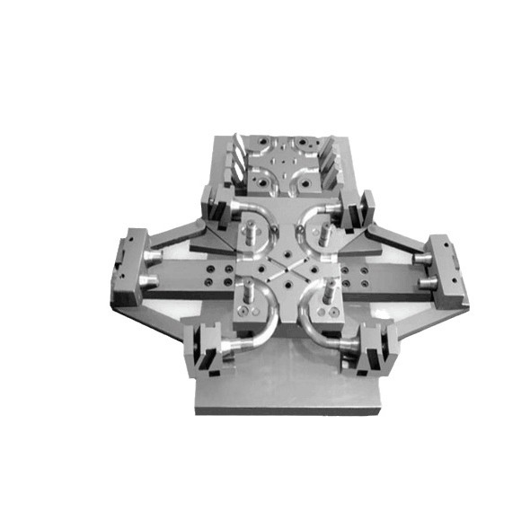
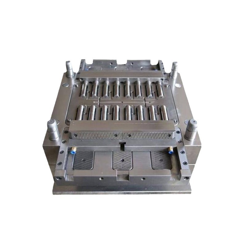
An injection mold is a hollow cavity designed to shape molten plastic into a specific form. The mold is typically made from hardened steel or aluminum. It’s engineered to withstand extreme conditions:
- High pressures: Up to 2,000 bar (about 29,000 psi)
- High temperatures: Molten plastic can exceed 300°C (570°F)
- Thousands or millions of cycles: Production molds run continuously
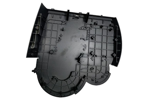
When molten plastic is injected into the mold, it fills every detail of the cavity. As it cools, it solidifies into the exact shape of the mold’s interior. The result is a finished part that matches the design perfectly—and can be reproduced thousands or millions of times with remarkable consistency.
Injection Molds in Everyday Life
You encounter injection-molded parts constantly:
- Smartphone housings
- Keyboard keys
- Kitchen utensil handles
- Automotive dashboards
- Medical syringes
- Toy figures
Each of these started as a design, was translated into a mold, and then produced in quantities from thousands to millions.
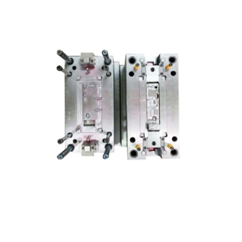
What Are the Key Components of an Injection Mold?
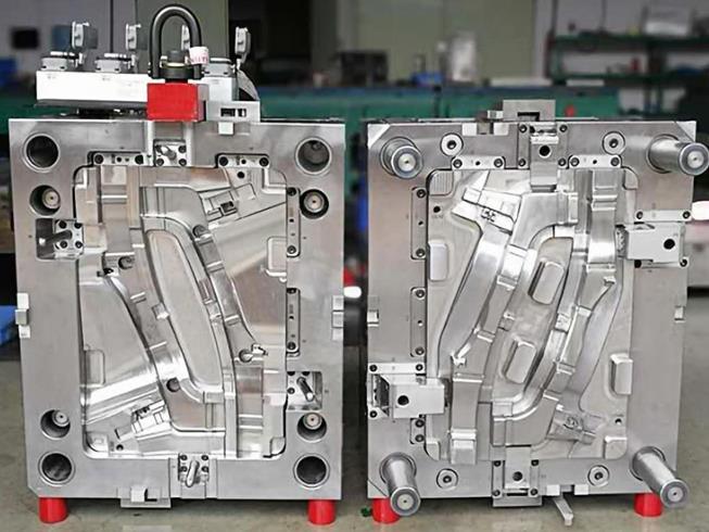
Mold Cavity: Shaping the Outside
The mold cavity is the space that determines the outer shape of the final product. It’s the negative impression of your part—the hollow form that the plastic fills.
| Cavity Type | Description | Best For |
|---|---|---|
| Integral cavity | Machined as a single solid piece | High rigidity, precision parts, high-pressure molding |
| Combined cavity | Assembled from multiple parts | Complex shapes, easier repair and modification |
Integral cavities offer superior dimensional stability. If you’re making small, precision electronic connectors, an integral cavity ensures accurate replication of fine details. But they’re expensive to modify—changing anything requires machining the entire block.
Combined cavities are more flexible. For complex shapes like toys with intricate geometries, combined cavities allow easier manufacturing and repair. If one section gets damaged, you replace only that piece, not the whole cavity.
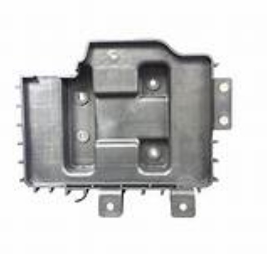
Mold Core: Shaping the Inside
The mold core forms internal features—holes, recesses, hollow areas. While the cavity shapes the outside, the core shapes what’s inside.
| Core Type | Description | Example |
|---|---|---|
| Integral core | Single-piece structure | Medical syringe—creates the internal channel |
| Combined core | Assembled from multiple parts | Automotive intake manifold—complex internal passageways |
| Movable core | Moves in and out during molding | Snap-on lid with undercuts—retracts to release the part |
Movable cores are especially important for parts with undercuts. A plastic container with a snap-on lid has internal hooks that lock the lid in place. Without a movable core, the part would be stuck in the mold. The core retracts, the part releases, and the cycle continues.
Runner System: The Pathway
The runner system is the network of channels that carries molten plastic from the injection machine nozzle to the mold cavities. Its job is to distribute plastic evenly to all cavities.
| Runner Shape | Characteristics |
|---|---|
| Circular | Lowest pressure drop, efficient flow, but more material waste and harder to machine |
| Trapezoidal | Easier to machine, good balance of flow and material use, common in standard molds |
For large-scale molds with many cavities, circular runners minimize pressure drop and ensure all cavities fill properly. For smaller molds, trapezoidal runners offer a cost-effective balance.
Gate: The Entry Point
The gate is the connection between the runner system and the mold cavity. It controls how plastic enters the cavity—flow rate, direction, and pressure.
| Gate Type | Description | Best For |
|---|---|---|
| Side gate | Located on the side of the cavity | Simple shapes, easy to manufacture and remove |
| Submarine gate | Hidden within the mold, self-cutting during ejection | Cosmetic parts where visible gate marks aren’t acceptable |
| Pin-point gate | Very small diameter | High-precision, small parts with tight tolerances |
Submarine gates are especially useful for cosmetic products. The gate cuts itself during ejection, leaving no visible mark on the finished part. Cosmetic containers, smartphone cases, and automotive interior trim often use submarine gates.
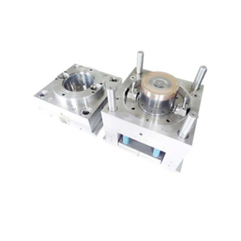
Ejector System: Releasing the Part
The ejector system pushes the finished part out of the mold after cooling.
Components:
- Ejector pins: Small rods that physically push the part
- Ejector plate: Coordinates all pins to move together
- Return pins: Reset the system when the mold closes
Without a properly designed ejector system, parts stick in the mold. That causes production delays, potential mold damage, and risk of part deformation.
How Does the Injection Molding Process Work?
Step 1: Mold Design
Every successful part starts with a well-designed mold. Designers consider:
Product geometry: Complex shapes may need movable cores or slides. CAD (Computer-Aided Design) software creates 3D models of the mold. Mold flow analysis simulates how plastic flows, identifying potential air traps or weld lines before steel is cut.
Material selection: Different plastics have different properties. A high-shrinkage material like polypropylene requires a larger cavity to compensate. A low-shrinkage material like ABS holds tighter dimensions.
Cavity layout: How many cavities? A 32-cavity mold for small buttons increases production but requires careful runner design to ensure even filling.
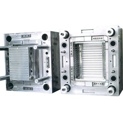
Step 2: Mold Manufacturing
Once the design is finalized, the mold is built.
Machining: CNC (Computer Numerical Control) machines cut the cavity and core from blocks of steel or aluminum. This requires skilled operators and advanced equipment to achieve tolerances as tight as ±0.01 mm.
Electrode machining (EDM): For complex geometries that CNC can’t reach, EDM uses electrodes to burn away material precisely. This creates sharp corners, deep ribs, and intricate details.
Heat treatment: After machining, mold components may be heat-treated to increase hardness and wear resistance. A mold for high-volume automotive parts needs this durability to withstand hundreds of thousands of cycles.
Assembly: All components—cavity, core, runner system, ejector system—are assembled. Precision alignment is critical. Dowel pins and screws hold everything in place. Misalignment leads to defective parts.
Step 3: Injection
The injection stage introduces molten plastic into the mold.
Plastic melting: Plastic pellets feed into a heated barrel. A rotating screw melts the material. Barrel temperatures are carefully controlled—for ABS, typically 200–250°C (390–480°F).
Injection into the mold: The screw forces molten plastic through the nozzle and into the runner system. Injection pressure ranges from 500 to 2,000 bar, depending on part size and complexity. A simple part might need 800 bar. A complex automotive component with thin walls may need 1,500–2,000 bar.
Injection speed matters too. Too slow, and the mold doesn’t fill completely. Too fast, and you get air traps or flash (excess plastic leaking out).
Step 4: Cooling
Once the cavity is filled, cooling begins.
Heat transfer: Cooling channels—typically filled with water—circulate through the mold, pulling heat away from the plastic. Efficient cooling prevents warpage and reduces cycle time.
Cooling time: Thicker parts need longer cooling. A 5 mm wall might require 30–60 seconds. A 1 mm wall might cool in 10–20 seconds. Too short, and the part deforms. Too long, and production slows.
Step 5: Ejection
After cooling, the mold opens, and the finished part is ejected.
Mold opening: The injection machine separates the two mold halves.
Ejector operation: The ejector plate moves forward, pushing ejector pins against the part. Pins must be positioned carefully to distribute force evenly. A delicate toy needs pins in the right spots to avoid breaking thin features.
Product removal: In automated lines, robots or conveyors collect the parts and move them to the next stage—quality inspection, trimming, painting, or assembly.
What Makes a Good Injection Mold?
A good injection mold combines several qualities:
| Quality | Why It Matters |
|---|---|
| Precision | Holds tight tolerances consistently, part after part |
| Durability | Withstands thousands or millions of cycles without wear |
| Efficient cooling | Reduces cycle time, prevents warpage |
| Easy maintenance | Worn components can be replaced without rebuilding the entire mold |
| Proper ejection | Releases parts cleanly without damage |
Conclusion
An injection mold is far more than a hollow block of steel. It’s a precision-engineered system of components—cavity, core, runner system, gate, and ejector system—working together to produce high-quality plastic parts at scale.
Understanding how molds work helps you design better parts, communicate more effectively with manufacturers, and avoid costly mistakes. Whether you’re launching a new product or optimizing an existing one, the mold is where it all starts.
FAQ
What is the difference between a mold cavity and a mold core?
The cavity forms the outside shape of the part. The core forms internal features like holes, recesses, and hollow areas. Together, they define the complete geometry of the finished product.
How long does an injection mold last?
Mold life depends on material and maintenance. A well-made steel mold can produce 500,000 to 1,000,000 cycles. Aluminum molds typically last 10,000 to 50,000 cycles. Regular cleaning, lubrication, and wear inspection extend life significantly.
What materials are used to make injection molds?
Most molds are made from steel—P20 for general use, H13 for high-temperature applications, or stainless steel for corrosion resistance. Aluminum is used for low-volume or prototype molds. The choice affects cost, durability, and lead time.
Why is cooling so important in injection molding?
Cooling takes up 50–80% of the total cycle time. Efficient cooling reduces cycle time, increases production output, and prevents warpage and internal stresses. A well-designed cooling system is essential for both quality and profitability.
What is mold flow analysis?
Mold flow analysis is computer simulation that predicts how molten plastic will fill the mold cavity. It identifies potential defects—air traps, weld lines, uneven filling—before the mold is built. This allows designers to optimize gate locations and cooling channels, preventing costly rework later.
Contact Yigu Technology for Custom Manufacturing
At Yigu Technology, we design and build precision injection molds for clients across industries—automotive, medical, consumer electronics, and more. Our engineers use advanced CAD and mold flow analysis to optimize designs before steel is cut. We combine precision machining, in-house EDM, and rigorous quality control to deliver molds that perform.
Whether you need a single-cavity prototype tool or a high-volume production mold with 32 cavities, we bring the experience and equipment to get it right.
[Contact Yigu Technology today] to discuss your project. Let’s turn your design into a mold that delivers consistent, high-quality parts.