For anyone involved in the design, commissioning, or maintenance of an injection molding operation, the Injection Moulding Diagram is the indispensable master blueprint. Far more than a simple drawing, it is a comprehensive visual language that communicates the complex interplay of mechanical, hydraulic, thermal, and electrical systems within a mold and its machine interface. Misinterpreting this diagram can lead to costly setup errors, production delays, or even safety incidents. This guide demystifies the Injection Moulding Diagram for mold designers, process engineers, and technicians. We will dissect its components, decode its symbols, and explain its critical role in ensuring efficient, safe, and repeatable production.
What Is an Injection Moulding Diagram?
An Injection Moulding Diagram is a detailed schematic drawing that provides a complete technical overview of an injection mold and its integration with the molding machine. It is not a single view but a collection of diagrams—cross-sectional, exploded, and schematic—that collectively define the mold's architecture and function. Its primary purposes are:
- Communication: Serving as the universal reference for designers, builders, mold setters, and maintenance personnel.
- Troubleshooting: Providing a roadmap for diagnosing issues related to filling, cooling, ejection, or safety.
- Documentation: Acting as a living record of the mold's design, essential for future repairs, modifications (ECOs), and reverse engineering.
Which Key Components Must Be Labelled?
A professional diagram clearly labels all critical subsystems. Omission of any can cause confusion.
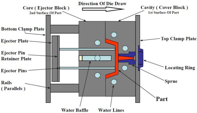
- Mold Base: Fixed Half (Cavity Plate) and Moving Half (Core Plate).
- Forming Components: Cavity Inserts, Core Inserts, Slides, Lifters.
- Feed System: Sprue Bushing, Runners, Gates (Hot Runner: Manifold, Nozzles, Valve Gates).
- Ejection System: Ejector Plate, Ejector Pins, Sleeves, Blades, Return Pins.
- Cooling System: Water Lines (Bubblers, Baffles), Connectors (Jiffy-tites).
- Guidance & Alignment: Leader Pins/Bushings, Interlocks.
- Machine Interface: Locating Ring, Clamp Slots, Sprue Puller.
How Does the Plastic Flow Path Appear in a Diagram?
The melt flow path is a critical narrative within the diagram. It is typically highlighted with a distinct color (often red) or a thick, dashed line.
- Path Illustration: The diagram traces the plastic's journey from the machine nozzle → sprue bushing → runners (cold or hot) → gates → cavity.
- Hot Runner Details: For hot runner systems, the diagram must show the heated manifold, individual nozzles, and thermocouple locations. Electrical schematics for heater circuits are often separate but referenced.
- Gate Callouts: Each gate is clearly marked with its type (edge, submarine, pin-point) and nominal dimensions.
What Symbols Differentiate Fixed vs. Moving Halves?
Clear visual demarcation between the stationary and moving sections is essential.
- Section Lines & Shading: The fixed half (attached to the machine's stationary platen) may be shown with a specific cross-hatch pattern or left unshaded. The moving half (on the moving platen) uses a different pattern.
- Centerline: A bold centerline often runs through the diagram, clearly separating the two halves when the mold is open.
- Annotation: Plates are explicitly labelled "FIXED HALF" and "MOVING HALF."
How Are Temperature and Pressure Sensors Illustrated?
These are the "eyes and ears" of the process and must be precisely located.
- Thermocouples (Temperature Sensors): Represented by a standard symbol (often a circle with a "TC" or a specific ISA/IEC symbol) and labelled (e.g., TC1, TC2). Their exact depth and location relative to the cavity or hot runner channel are critical dimensions.
- Pressure Transducers: Used in scientific molding, they are shown embedded in the cavity or runner system with a specific symbol and callout (e.g., PT1). Their location directly impacts the quality of data for cavity pressure monitoring.
What Do Color Codes Indicate in Piping Layouts?
Color-coding on cooling and hydraulic lines provides instant visual recognition, reducing setup errors.
- Standard Industry Practice:
- Blue Lines: Coolant IN (from chiller to mold).
- Red Lines: Coolant OUT (from mold back to chiller).
- Green Lines: Temperature Control Unit (TCU) circuits for hot runner manifolds (if separate).
- Yellow/Orange Lines: Hydraulic lines for core pulls or valve gate actuation.
- Diagram Legend: A comprehensive color code legend must be included on the diagram sheet.
How to Represent Cooling Circuits Clearly?
The cooling layout is often a separate, dedicated schematic view due to its complexity.
- Circuit Numbering: Each independent cooling loop (e.g., Core Loop A, Cavity Loop B) is numbered sequentially.
- Flow Direction: Arrows indicate the direction of coolant flow (IN → through baffle/bubbler → OUT).
- Connection Points: All external connections (female thread ports) are labelled with their circuit number (e.g., "IN-A", "OUT-A") and thread size (e.g., NPT 1/4").
- Zoning: Complex molds may have multiple temperature zones, each with its own circuit.
What Safety Elements Should Be Highlighted?
Safety is paramount. The diagram must flag all potential hazards.
- Interlocks: Show the position of mechanical or electrical safety interlocks that prevent mold closing if an ejection plate is not fully retracted.
- Proximity Switches: Indicate sensors that confirm slide or core positions before the mold can close.
- Hydraulic Core Locking: For large slides, the diagram should show lock cylinders that hold the slide in place during injection to prevent "core back."
How to Depict Ejector Systems and Actions?
The ejection system's movement and timing are often shown in a sequence or with dual-state diagrams.
- Ejector Grid: A top-down view of the ejector plate showing the size, type (pin, sleeve, blade), and location of every ejector component. Each is given a unique identifier (E1, S1, B1).
- Ejection Stroke: A side-view section typically includes a dimension for the maximum ejection stroke.
- Lifter/Slide Actions: Complex mechanisms like lifters or angled pin slides are shown in both their molded (closed) and ejected (open) positions to illustrate their travel path.
Which Software Tools Create Professional Diagrams?
While 3D CAD is king for design, 2D schematics remain essential for clarity.
- Industry-Standard CAD: AutoCAD and SolidWorks Drawing are most common. They allow for precise layers, standardized symbols, and linking to 3D models for automatic Bill of Materials (BOM) generation.
- Specialized Mold Design Software: Tools like MoldWorks or TopSolid have libraries of standard mold components and automated drawing generation tools.
- Process: The diagram is generated from the 3D CAD model, with layers turned on/off to create clear views of different systems (cooling, ejection, etc.).
How to Update Diagrams for Engineering Changes?
An outdated diagram is worse than no diagram at all. A strict Engineering Change Order (ECO) process must govern updates.
- The change is requested and approved via an ECO form.
- The original CAD model is modified.
- All associated diagram sheets are updated, and a revision cloud highlights the changed area.
- The diagram's title block revision letter is incremented (e.g., Rev A → Rev B), and the change is logged.
- Updated drawings are distributed, and old versions are archived.
What Common Mistakes Must Be Avoided?
- Missing Critical Dimensions: Omitting the depth of water lines or the location of thermocouples.
- Overcrowding: Trying to show every system in one view. Use multiple, cleanly layered sheets.
- Inconsistent Symbolism: Not adhering to company or industry-standard symbols.
- No BOM: Failing to include a detailed Bill of Materials with part numbers, materials, and quantities.
Conclusion
An Injection Moulding Diagram is far more than a drawing; it is the foundational communication tool and operational manual for a precision mold. Its clarity and completeness directly influence setup speed, process stability, maintenance efficiency, and overall safety. By mastering its language—from the color-coded flow of coolant to the precise symbols for sensors and safety devices—teams can transcend operational ambiguity. In a world where downtime is measured in dollars per minute, a professionally executed diagram is not an option; it is a critical component of manufacturing excellence and a hallmark of a well-engineered mold.
FAQ on Injection Moulding Diagrams
Is the Injection Moulding Diagram the same as a mold design drawing?
It is a key part of it. The mold design drawing package includes detailed part drawings for each component (cores, cavities, plates). The Injection Moulding Diagram is the schematic overview that shows how all those components interact as a system, focusing on function and interfaces.
Who is the primary user of this diagram?
It serves multiple users: Mold Designers (to communicate intent), Mold Makers (to build it), Process Technicians/Mold Setters (to connect water, hydraulics, and set up correctly), and Maintenance Personnel (for troubleshooting and repair).
Why are cooling circuit diagrams so important?
Improper cooling is a leading cause of long cycle times and part warpage. A clear cooling diagram ensures the mold is connected correctly to achieve balanced cooling, where all areas of the mold cool at the intended rate. A mix-up in connections can double cycle time or scrap every part.
What is the most overlooked element in these diagrams?
Safety and sequence interlock details. Diagrams often focus on form and cooling but omit the sensors and switches that prevent the mold from crashing itself—a costly oversight.
Can a diagram be entirely replaced by a 3D model?
Not entirely. While 3D PDFs and interactive models are incredibly valuable for visualization, the 2D schematic diagram remains superior for quickly conveying specific system layouts (like cooling line routing), displaying callouts, and providing a printable, at-a-glance reference on the shop floor.
Contact Yigu technology for custom manufacturing.
At Yigu Technology, we understand that precision manufacturing begins with precision communication. Our mold design process is built on creating exceptionally clear, comprehensive, and accurate Injection Moulding Diagrams. These documents form the backbone of our collaboration with clients and ensure flawless tooling setup and production. Our expertise spans complex multi-cavity, hot runner, and sequential valve gating systems, all meticulously documented for your team's success.
If you require a manufacturing partner that values clarity, precision, and thorough documentation from the diagram stage forward, partner with us.
Contact Yigu Technology today to discuss your project and see examples of our professional technical documentation.