In the world of plastic injection molding, the choice of a runner system is a fundamental decision that impacts part quality, production efficiency, and unit cost. Cold runner molds represent the traditional and most widely understood technology. They channel molten plastic from the machine nozzle to the part cavities through machined channels that cool and solidify along with the parts. While often contrasted with hot runner systems, cold runner molds remain the optimal, economical choice for a vast range of applications. This comprehensive guide delves into the mechanics, design nuances, material considerations, and economic calculus of cold runner molds, providing manufacturing engineers and decision-makers with the insights needed to leverage this robust technology effectively.
What Are Cold Runner Molds?
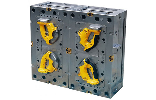
A cold runner mold is a tooling system where the flow channels (runners) that deliver plastic from the injection molding machine's sprue to the part cavities are actively cooled by the mold's temperature control system. These runners solidify completely during the cooling phase of the cycle. Once the mold opens, the entire molded output—including the finished parts and the solidified runner network—is ejected. This solidified runner material, often called regrind or scrap, is typically separated from the parts, often manually, and can be recycled by grinding and reintroducing it into the process, a practice known as regrind blending. The system's simplicity lies in its direct thermal management: both the part and the runner are cooled and ejected together.
How Do Cold Runners Differ from Hot Runners?
The core distinction lies in thermal management and material flow.
- Cold Runner Molds: The runner is a cooled part of the mold. Material solidifies in the runner, creating scrap that requires separation and handling. This system offers lower initial tooling costs and exceptional material flexibility, as there is no risk of material degradation in heated manifolds.
- Hot Runner Molds: The runner system is maintained in a molten state by internal heaters. Only the part cavities cool and solidify. This system eliminates solid runner scrap, enabling runners molding, potentially faster cycles, and automated, gate-less parts.
Table: Cold Runner vs. Hot Runner Systems
| Feature | Cold Runner Molds | Hot Runner Molds |
|---|---|---|
| Initial Tooling Cost | Lower (simpler construction) | Significantly higher (complex manifolds, heaters, controls) |
| Material Waste | Generates solidified runner scrap | Minimal to zero runner scrap |
| Cycle Time Impact | Longer (runner must cool) | Potentially shorter (only part cools) |
| Material Flexibility | Excellent. Handles heat-sensitive, shear-sensitive, or abrasive materials with ease. | Limited. Risk of material degradation or "hang-up" in heated channels. |
| Color/Material Change | Slower (requires purging solidified material) | Faster for hot-to-hot changes, but complex for dissimilar materials. |
| Best For | Short to medium production runs, prototyping, highly filled/abrasive materials, frequent color changes. | High-volume production, engineering resins where regrind is undesirable, automation-focused lines. |
Which Gate Designs Are Most Common?
The gate is the critical transition point from the runner to the part cavity. Cold runner molds accommodate a wide variety of gate types.
- Edge Gate: The most common and simple. Located on the part perimeter, it's easy to machine and trim but leaves a visible witness mark.
- Submarine (Tunnel) Gate: A small, angled gate that shears off automatically upon ejection, leaving a minimal mark. Ideal for automated degating and cosmetic parts. Its size and angle require precise calculation to prevent shear-induced material issues.
- Direct (Sprue) Gate: Used for single-cavity molds. The sprue feeds directly into the part. It offers excellent filling but leaves a large mark and creates high stress at the gate location.
- Diaphragm Gate: Used for cylindrical parts. It provides symmetrical filling, minimizing warpage, but requires extensive post-machining to remove the gate.
What Materials Perform Best in Cold Runners?
Cold runner molds are virtually universal in material compatibility. However, they are particularly advantageous for:
- Heat-Sensitive Materials: PVC, certain POM (acetal), and some TPEs can degrade if held at melt temperature in a hot runner manifold. Cold runners eliminate this residence time risk.
- Abrasive or Highly Filled Materials: Materials with glass fiber, minerals, or other fillers rapidly wear out hot runner system components like valve pins and gate seats. The simple, robust channels of a cold runner mold are more wear-resistant and cheaper to maintain or polish.
- Materials with Stringing or Dripping Tendencies: Some polymers, like standard polypropylene (PP), can "string" in hot runner systems when the mold opens. This is not an issue in a fully solidified cold runner.
How to Size Runner Systems for Balanced Fill?
Achieving balanced fill—where all cavities in a multi-cavity mold fill simultaneously and uniformly—is paramount for part consistency. In cold runner molds, this is done through geometrically balanced runner layouts (e.g., "H-pattern" or "radial") and proper runner sizing.
- Runner Diameter: Sizing is based on part volume, material flow characteristics, and the need to maintain pressure. An undersized runner causes excessive pressure drop and premature freezing; an oversized runner increases cycle time and scrap.
- The "Runner Sizing Rule": For a geometrically balanced system, the flow length from the sprue to each cavity should be identical. This is achieved by using runner diameter calculations to ensure equal flow resistance. For example, a mold producing 8 medical syringes might use a primary runner of 6mm, branching into secondary runners of 5mm, feeding tertiary runners of 4mm leading to each gate. Computational Mold Flow Analysis (CFD) is the modern standard for optimizing this design virtually before steel is cut.
What Cycle-Time Impacts Should Be Expected?
The primary cycle time penalty in a cold runner mold is the additional cooling time required for the runner system to solidify enough for ejection. This time is dictated by the thermal properties of the plastic and the thickest cross-section of the runner, which is often significantly larger than the part wall. For a part with a 2mm wall, a 6mm diameter runner becomes the cycle-time driver, as it takes roughly 9 times longer to cool (cooling time is proportional to the square of the thickness). This makes runner cross-sectional design a direct lever for cycle time optimization.
How to Minimize Regrind and Waste?
Managing the inevitable scrap from cold runner molds is key to economics and sustainability.
- Design Efficient Runner Layouts: Use the smallest runner diameters that allow for proper filling and packing. Implement naturally balanced layouts to prevent over-packing some cavities (which creates defective parts and waste).
- Optimize Regrind Management: Implement a closed-loop regrind blending system. Consistently blend a controlled percentage (e.g., 10-30%, depending on the material and part requirements) of clean, granulated runner scrap back with virgin material. This requires dedicated granulators, blending equipment, and strict quality control to prevent contamination or degradation.
- Consider Cold Slug Wells: Design proper cold slug wells at the end of runners to capture the initial, cooled material from the nozzle, preventing it from blocking gates and causing short shots.
Cost Analysis: Is Cold Runner Economical for Your Volume?
The economic breakpoint between cold and hot runners is not fixed but depends on several variables. Cold runner molds shine when:
- Production volumes are low to medium (e.g., under 500,000 parts).
- Part size is relatively small, so the mass of the runner scrap is a small percentage of the shot weight.
- Material cost is low (e.g., commodity polyolefins), making the value of the scrap less significant.
- Tooling budget is constrained. The lower upfront cost of a cold runner mold improves project ROI for shorter runs.
A detailed analysis must compare: Cold Runner Tooling Cost + (Material Cost per shot including scrap) x Production Volume versus Hot Runner Tooling Cost + (Material Cost per shot with no scrap) x Production Volume. For a recent project involving a filled nylon automotive clip, the cold runner mold saved over $40,000 in initial tooling. Given an annual volume of 200,000 parts, the material cost of the runner scrap was calculated to be under $2,000/year, making the cold runner the clear economic choice.
How to Optimize Venting and Cooling Layouts?
Because cold runner molds involve solidifying large plastic volumes (the runners), thermal management is critical.
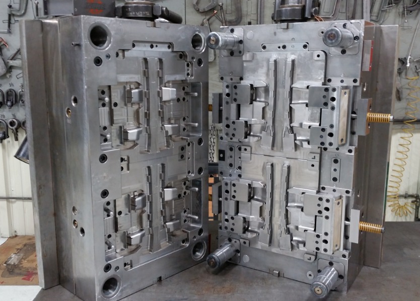
- Cooling Layout: Place cooling lines as close as possible to both the part cavities and the runner channels. A common mistake is to focus cooling only on the part, neglecting the runner. This leads to extended cycle times. For a three-plate mold, cooling channels are essential in both the cavity plate and the runner stripper plate.
- Venting: Trapped air can cause burns, short shots, and dimensional issues. Vents must be placed at the end of fill, not just in the part cavities but also along the runner system, especially at junctions and ends of runners. Proper venting ensures clean, complete parts and reduces the required injection pressure.
Conclusion
Cold runner molds are a testament to robust, effective engineering. While hot runners capture attention for high-volume automation, cold runner systems offer unparalleled flexibility, material compatibility, and lower entry costs. Their efficiency hinges on meticulous design—balancing runners, minimizing cross-sections, and integrating smart cooling and venting. For manufacturers engaged in short runs, prototyping, or working with challenging materials, mastering the cold runner mold is not a compromise but a strategic advantage. It provides a controllable, predictable, and economical pathway to high-quality plastic parts.
FAQ on Cold Runner Molds
What is the biggest disadvantage of a cold runner mold?
The primary disadvantage is the generation of solid plastic waste (scrap) with every cycle. This requires handling, separation, and regrind management, adding labor, material cost, and complicating fully automated production lines.
Can cold runner molds be automated?
Yes, with proper design. Using submarine gates allows for automatic degating upon ejection. Robots can then pick the entire shot (parts and runner) and place it into a granulator that separates parts from runners. However, it is generally less seamless than hot runner automation.
How do you calculate the appropriate runner size?
Runner sizing is based on the part volume, material viscosity, and flow length. Empirical rules (e.g., starting with a diameter of 1.5x the part's maximum wall thickness) and textbook formulas exist, but today, computer-aided engineering (CAE) flow simulation is the industry standard for precise, optimized sizing to balance pressure drop and cooling time.
Is a three-plate mold always a cold runner mold?
Essentially, yes. A three-plate mold is a specific type of cold runner mold design. It uses an extra plate to automatically separate the runner from the parts during ejection, allowing the sprue and runners to be ejected via a different path than the parts, which is crucial for center-gated parts in multi-cavity layouts.
When is a cold runner mold absolutely the wrong choice?
It is generally the wrong choice for very high-volume production (millions of parts) of small items where the runner scrap mass can equal or exceed the part mass. The cumulative material waste cost and slower cycles will outweigh the lower tooling investment. It's also suboptimal for ultra-cleanroom environments where handling regrind poses a contamination risk.
Contact Yigu technology for custom manufacturing.
Navigating the choice between cold runner and hot runner systems requires expertise tailored to your specific part, material, and production goals. At Yigu Technology, our engineering team possesses deep, hands-on experience in designing and manufacturing high-performance cold runner molds that optimize cycle time, material usage, and part quality. From initial DFM analysis and runner balancing to efficient cooling design and regrind strategy consulting, we provide end-to-end solutions.
Let us help you build the most efficient and cost-effective molding system for your project. Contact Yigu Technology today for a detailed project review and quotation.